P/N 960-100189RA_Rev. A {EDP #148850} © 2009, Japan CashMachine Co., Limited
VEGA™ Series
BankNote Validator
Appendix A
This section provides Troubleshooting instructions
for the VEGA BankNote Validator. The following
information is contained in this Section:
•
Introduction
•
Troubleshooting Overview
•
Fault Table Listings
•
Performance Tests
•
LED Diagnostic Codes
Introduction
Most Validator failures are due to minor causes.
Before replacing any parts, make sure that all
Assembly and Circuit Board Connectors are prop-
erly fitted, and the Harness is properly connected.
Faulty Banknote acceptance by the Validator por-
tion of the VEGA is often caused when dust or Iron
powder adhere
s to the Identification Sensor, Mag-
netic Sensor or Transport Belt. Clean the Acceptor
Section
first, then observe the operating state of the
Acceptor in detail when re-initializing power. This
observation is important in locating any failure
causes and the possible fault area. If the Acceptor
Head has to be repaired by disassembling it,
always re-calibrate the Sensors following a repair.
Perform all repairs by referring to theCalibration
Procedures in Section 6 of this Service Manual,
andDissassembly/Reassembly in Section 4 of this
Service Manual.
Troubleshooting Overview
The VEGA allows the operator to perform fault
diagnosis by checking various fault Table listings
against the symptom
, and survey the cause(s) of
any failure occurrences during the process.
After determining the cause of the failure
, execute
the particular Performance Test, perform a Sensor
re-adjustment and then repair the VEGA Unit by
replacing any appropriate parts deemed necessary.
Fault Table Listings
Table A-1 through Table A-3 list the various
possible VEGA fault conditions that
can occur and
the necessary actions required to correct them.
Malfunction LED Error Code
The VEGA Unit’s Front Panel Bezel LEDs will be
flashing when errors or Banknote rejects occur.
Table A-1, Table A-2 and Table A-3 list the pos-
sible Malfunction LED Error Codes that are ident-
ified
by various LED flash counts and Colors.
When Error Codes and Reject Codes are not
indicated (e.g., VEGA’s Bezel LEDs are not lit) or
not identified in detail,
find the cause in the follow-
ing Tables and take the appropriate action.
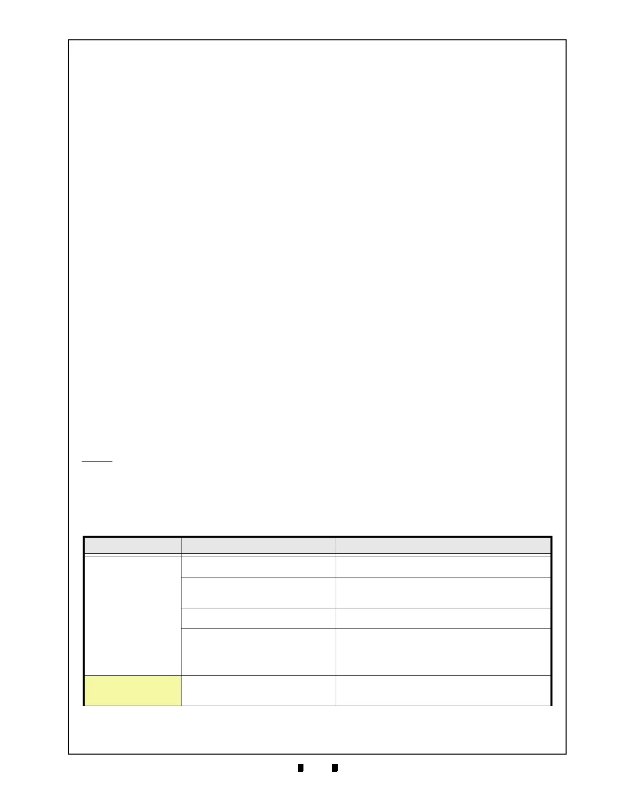
Table A-1 LED Diagnostics
Symptoms Causes Solutions
VEGA is not working
(VEGA’s Bezel LED is not
lig
hting)
The power is not supplied.
Check that the Interface connectors are properly connected.
Verify that the Power Supply meets its specification.
Program is not actuated.
(The Software download has not been
compl
eted correctly).
Re-download the correct software.
(Refer to VEGA Service Manual for
details regarding proper
“Software Download” procedures).
CPU Board or SUB Board is malfunctioning.
Check that the VEGA’s internal Harnesses and Connectors are
pr
operly fitted.
Not communicated with the Host Machine.
Different Interfaces (DIP Switches) are set on
eac
h the VEGA and the host machine.
Interface (DIP Switches) settings are not
cor
rect.
Check that the Interface settings and the DIP Switch settings
me
et their design specifications.
(See “DIP Switch Configurations” on page 2-2
).
VEGA is not working
(VEGA’s Bezel LED is not
fla
shing yellow)
ROM malfunctioning or RAM malfunctioning.
Identify the error flashing pattern and locate the error by
r
eferring to the Error Codes Table; then perform the necessary
action required (See Table A-2).

 Loading...


