P/N 960-100189RA_Rev. A {EDP #148850} © 2009, Japan CashMachine Co., Limited
Section 6 VEGA™ Series BankNote Validator Calibration and Testing
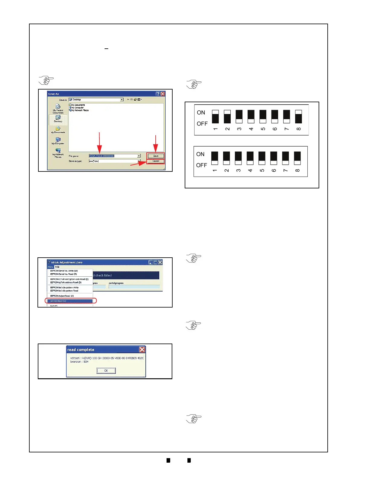
3. The Screen shown in Figure 6-79 will appear
allowing the data to be saved on the PC.
Mouse-click on the “
Save
” Screen Button
(See Figure 6-79 a) to record the data results on
the PC, or Mouse-click on the “
Cancel
” Screen
Button (See Figure 6-79 b) to end the adjustment
procedure without saving the data.
4. Open the Saved Data File on the PC (e.g., Figure
6-79 example
VEGA_Read_000000000
in this
case), and enable it to confirm that
the newly
saved adjustment data is correct.
Reading the VEGA Software Version
Perform following steps when reading a VEGA
Unit’s Software Version.
1. Mouse-click and hold-down on the “
VEGA_
Adjustment
” Tool Bar “
Menu
” selection, then
slide-down select “
version Read (V)
” from the
Pull-Down Menu selections (See Figure 6-80).
2. The VEGA Unit will respond by sending the
“
read complete
” current Software Version infor-
mation shown on the Figure 6-81 Dialog Screen
to the PC.
3. Mouse-click on the Dialog Screen’s “
OK
” Screen
Button to accept the “read” state reported.
Non-PC Calibration Procedure
Refer to Figure 6-16 for details concerning Tool
requirements and Harness connections to perform
this procedure without
a PC.
Begin the Non-PC (No Written Serial No.)
Calibration Procedure as follows:
1. Turn the VEGA Unit’s power OFF.
2. Set DIP Switch Block No. 1, Switches #1, #2 &
#8
ON, and set DIP Switch Block No. 2,
Switches ALL OFF as shown in Figure 6-82.
3. Turn the VEGA Unit’s power ON. the Front
Panel LED will slowly blink at a Green Color
rate.
4. Set DIP Switch Block No. 1, Switch #1 OFF.
5. When moving into the Adjustment Mode, the
Fron
t Panel LED will slowly blink at a Cyan
Color rate.
6. Set DIP Switch Block No. 2, Switch #1 ON.
This action performs the Entrance Sensor’s
adjustment
Procedure without Reference Paper in
place (Keep DIP Switch Block No. 2, Switch #1
ON until receiving a Screen instruction to turn it
OFF).
7. Once the Entrance Sensor’s non-paper adjust-
ment is complete, the Front Panel LED will
slow
ly blink at a White light rate.
8. Set the White Reference Paper in place (
See Ref-
erence Paper Usage
on page 6-5
of this Section).
9. Set DIP Switch Block No. 2, Switch #2 ON.
This action performs the Validation Sensor’s
adjustments
using the White Reference Paper.
(Keep DIP Switch Block No.2, Switch #1 & #2
ON until receiving Screen instruction to turn it
OFF).
NOTE: The adjustment data cannot be read
from the PC unless it saved first.
Figure 6-79 Save Adjustment Results Screen
Figure 6-80 Menu Bar Pull-Down Selections 8
Figure 6-81 Software Version Read Complete
Dialog Screen
NOTE: DIP Switch Block No.3 settings are
not required to perdorm this Calibration
Procedure.
DIP Switch Block No.1
DIP Switch Block No.2
Figure 6-82 Non-PC Calibration DIP Switch Block
Initial Settings
NOTE: The Adjustment process will begin
at Step 6. Do not touch the VEGA Unit
while it is adjusting, otherwise the adjust-
ments will not accurately calibrate the Unit.
NOTE: During the adjustment process, the
Front Panel LED will flash a Cyan Color at
a high rate of speed.
NOTE: During the adjustment process, the
Front Panel LED will flash White Light at a
high rate of speed.

 Loading...


