P/N 960-100189RA_Rev. A {EDP #148850} © 2009, Japan CashMachine Co., Limited
Section 6 VEGA™ Series BankNote Validator Calibration and Testing
Calibration Procedures
Perform the following Calibration Procedures for
the Intake Sensors, the Validation Sensors and the
Edge Sensors within the VEGA Unit.
W
HEN
TO
C
ALIBRATE
When removing or replacing Circuit Boards,
calibrate them in the following order:
1. Sensor Boards (Upper or Lower).
2. CPU Board.
3. Sub-Sensor Board.
C
ALIBRATION
T
YPES
There are two (2) ways to preform the Calibration
Procedures:
•
Calibration using a PC
•
Calibration without using a PC
Workbench Calibration Tool Require-
ments
The following tools are required to adjust the
VEGA Unit’s Sensors:
•
VEGA Unit
•
PC (OS: Windows XP)
•
Power Suply (e.g., UAC, MIB232, etc.)
•
USB Cable (A Terminal & Mini-B Terminal)
•
Adjustment Program (
VEGA_Adjustment.exe
or VEGA_Adjustment_Zero.exe
)
•
White Reference Paper KS-318 (Part #146172)
(See Figure 6-14)
•
Black Reference Paper KS-319 (Part #146173)
(See Figure 6-14)
•
Harness.
Review Figure 6-2, Figure 6-4 and Figure 6-15 for
Calibration Mode Harness interconnect
ion details.
Calibration Preparation
This Calibration Preparation section provides the
following two (2) illustrated methods for Cal-
ibrating a VEGA Unit:
1. Figure 6-15 illustrates the Calibration Connec-
tion Tools and Harness configurations necessary
when
using a PC for Calibration.
2. Figure 6-16 illustrates the Calibration connection
Tools and Harness configurations necessary
when
calibrating WITHOUT using a PC for
calibration.
Review Figure 6-3 to identify the VEGA Unit’s
DIP Switch, LED and External Port Locations.
NOTE: If the word “Manual” appears in the
“Reset” Pull-down Menu (Review Figure 6-
10 b), the Front Panel LED will sustain a
steady Blue Color. In this case, Return to
the Start-up condition by pressing the
adjacent “Manual Reset” Screen Button
(Review Figure 6-10 c) located to the right
of the Pull-down Menu (The Front Panel
LED will then blink at a Green Color rate).
NOTE: If a download error occurs, the
Front Panel LED will light a Red Color.
Figure 6-13 Completed Screen
NOTE: If any Sensor is dirty due to foreign
objects or other such debris adhering to it,
calibration will not be accurate. Be sure to
clean all of the VEGA Unit’s Sensors before
performing a Calibration Procedure (
See
“Cleaning Procedure” on page 2-5 & “VEGA
Sensor Cleaning Locations” on page 2-6 of this
Service Manual for Sensor cleaning instructions
).
NOTE: Use the PC to perform a written
Serial Number Calibration when replacing a
CPU Board. The CPU Board contains a
unique Serial Number, so its data identity to
related files disappears when the CPU
Board is replaced. This condition may
cause performance of the VEGA to stop,
depending on the related Interfaces set to
operate with the particular VEGA Unit.
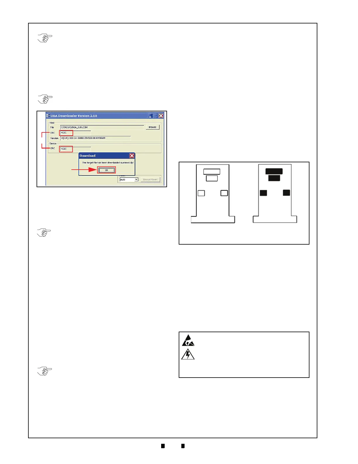
KS-318
KS-319
JAC Part #500-100222R
EDP #146172
JAC Part #500-100233R
EDP #146173
Figure 6-14 Reference Paper Types
WARNING: Ensure that the VEGA Unit’s
power is OFF when connecting any
Harnesses to the Unit. Connecting a
Harness while the power is ON may
damage the VEGA, the software Tool or
cause a personal electrical shock.

 Loading...


