P/N 960-100189RA_Rev. A {EDP #148850} © 2009, Japan CashMachine Co., Limited
Installation/Operation VEGA™ Series BankNote Validator Section 2
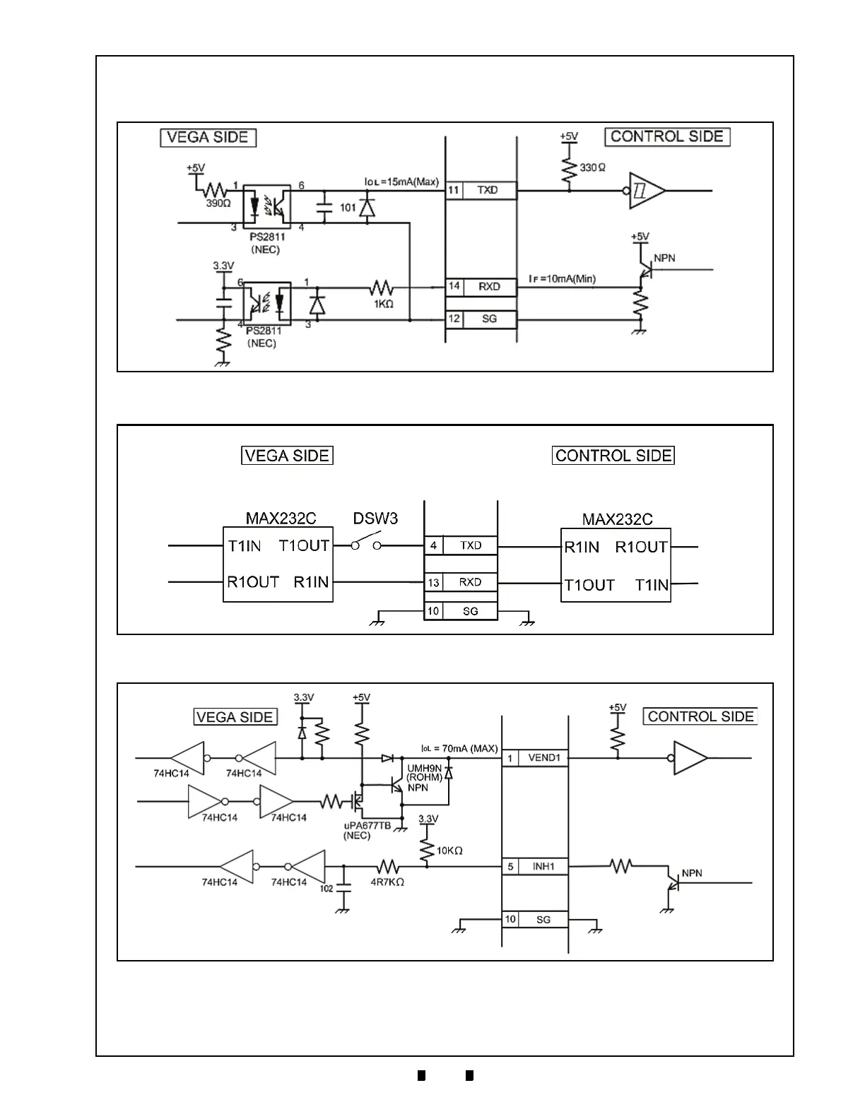
Standard Interface Circuit Schematics
Figure 2-14 illustrates the VEGA Photo Coupler Circuit Interface Schematic Diagram.
Figure 2-15 illustrates the VEGA RS-232C Circuit Interface Schematic Diagram.
Figure 2-16 illustrates the VEGA ccTalk Circuit Interface Schematic Diagram.
Figure 2-14 VEGA Photo Coupler Circuit Interface Schematic Diagram
Figure 2-15 VEGA RS-232C Circuit Interface Schematic Diagram
Figure 2-16 VEGA ccTalk Circuit Interface Schematic Diagram

 Loading...


