P/N 960-100189RA_Rev. A {EDP #148850} © 2009, Japan CashMachine Co., Limited
Section 6 VEGA™ Series BankNote Validator Calibration and Testing
P
ERFORMANCE
T
ESTS
A
CTIVATION
Perform following steps to activate the VEGA
Unit’s self contained Performance Tests:
1. Set DIP Switch Block DS1, Switch #1 to ON.
2. Turn the VEGA Unit’s power ON, and the
Performance Test Mode will activate.
Table 6-2 on page 6-16 lists the various Perfor-
mance Test DIP Switch Setting configurations for
ea
ch Test Type.
Performance Test Initiation
Set the various DIP Switches for each test listed in
Table 6-2 after the Performance Test Mode is
activated. Once the two (2) DIP Switch Block
Switches are set, set
DIP Switch DS1, Switch #1
OFF to begin each test.
The following information de
scribes each test in
detail.
DIP S
WITCH
T
EST
Perform following steps to test the functionality of
each DIP Switch Block:
1. Ensure that the VEGA Unit’s Power is OFF.
2. Set all Switches on DIP Switch Block DS1 and
DIP Sw
itch Block DS2 to ON as indicated in
Table 6-2 for this test.
3. Turn the VEGA Unit’s power ON.
4. Set DIP Switch Block DS1, Switch #1 OFF.
Wh
en the DIP Switch test begins, the Front Panel
LED will extinguish (goes out).
5. Set the ODD numbered DIP Switches (i.e., DIP
Switch
Block DS1 Switches #3, #5, & #7 and
DIP Switch Block DS2 Switches #1, #3, #5, &
#7) to OFF. The Front Panel LED Display will
blink at a Ye ll ow Color rate.
6. Set the EVEN numbered DIP Switches (i.e., DIP
Swi
tch DS1 Switches #2, #4, #6 & #8 and DIP
Switch DS2 Switches #2, #4, #6 & #8) to OFF.
The Front Panel LED Display will blink at a Blue
Color rate if all of the DIP Switches function
correctly.
F
EED
M
OTOR
F
ORWARD
R
OTATION
T
EST
Perform the following steps to test the normal
forward rotation functionality
of the Feed Motor:
1. Ensure that the VEGA Unit’s Power is OFF.
2. Set DIP Switch Block DS1, Switch #1 ON as
indicated in Table 6-2 for this test.
NOTE: The Multi-Color Indication LED is
located on the main Circuit Board below the
VEGA Unit’s Bezel (See Figure 1-4 on
page 1-4 of this Service Manual for details).
NOTE: When the VEGA Performance Test
Mode begins, the Front Panel LED will
slowly blink at a Green Color rate.
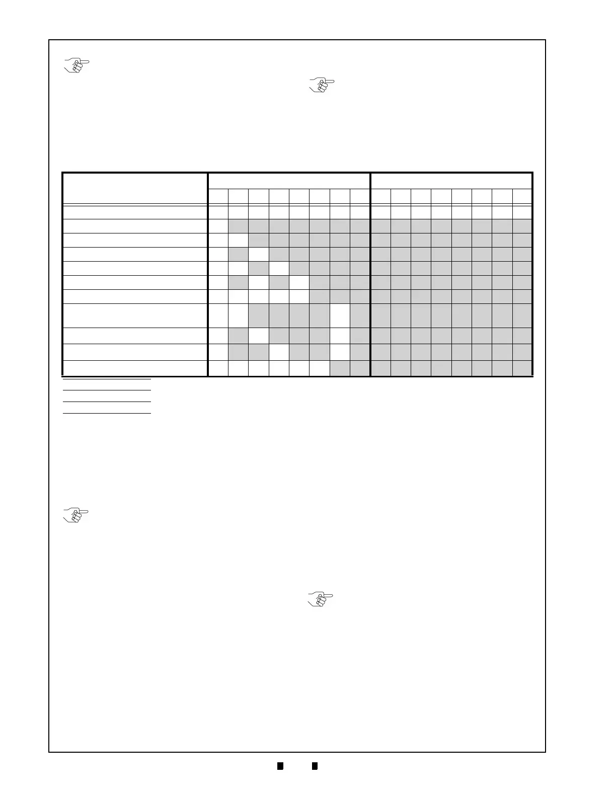
Table 6-2 Performance Test DIP Switch Configuration Settings
Test Type
DIP Switch Block 1 Switch Number DIP Switch Block 2 Switch Number
1 2 3 4 5 6 7 8 1 2 3 4 5 6 7 8
DIP Switch Test ON ON ON ON ON ON ON ON ON ON ON ON ON ON ON ON
Feed Motor Normal Rotation Test
ON OFF OFF OFF OFF OFF OFF OFF OFF OFF OFF OFF OFF OFF OFF OFF
Feed Motor Reverse Rotation Test ON
ON OFF OFF OFF OFF OFF OFF OFF OFF OFF OFF OFF OFF OFF OFF
Stacker Motor Test
ON OFF ON OFF OFF OFF OFF OFF OFF OFF OFF OFF OFF OFF OFF OFF
Aging Test ON
ON OFF ON OFF OFF OFF OFF OFF OFF OFF OFF OFF OFF OFF OFF
Off-line Banknote Acceptance Test
ON OFF ON OFF ON OFF OFF OFF OFF OFF OFF OFF OFF OFF OFF OFF
Sensor Test ON ON ON ON
ON OFF OFF OFF OFF OFF OFF OFF OFF OFF OFF OFF
Stand-by Color Indication
(Cycling Rainbow Grad
ation)
a
ON ON OFF OFF OFF OFF ON OFF OFF OFF OFF OFF OFF OFF OFF OFF
Stand-by Color Indication (Green)
b
ON OFF ON OFF OFF OFF ON OFF OFF OFF OFF OFF OFF OFF OFF OFF
Stand-by Color Indication (Blue)
c
ON OFF OFF ON OFF OFF ON OFF OFF OFF OFF OFF OFF OFF OFF OFF
ccTalk Encryption Code Initialization
d
ON ON ON ON ON ON OFF OFF OFF OFF OFF OFF OFF OFF OFF OFF
a. See “Stand-by Mode LED Assignment Indication” on page 2-3 for making the “Rainbow” setting (Gradation).
b. See “Stand-by Mode LED Assignment Indication” on page 2-3 for making the GREEN setting.
c. See “Stand-by Mode LED Assignment Indication” on page 2-3 for making the BLUE setting.
d. See “Rewriting cc-Talk Encryption Code (Initialize)” on page 2-3 for making the setting.
NOTE: After performing an “Off-line”
Banknote Acceptance Test, turn the VEGA
Unit’s power OFF to move to the next test.
Unless the power is turned OFF, the next
test will not run! Reset DIP Switch DS1,
Switch #1 to ON to begin the next test.
Re-apply power to re-enter the Perform-
ance Test Mode. The remaining tests can
then be completed by selecting the DIP
Switch settings for the next test desired.
NOTE: If the DIP Switches were set
incorrectly during the test, the Front Panel
LED Display will flash Red, indicating a test
failure. However, if the DIP Switches were
set correctly, and the LED still flashes Red,
then a DIP Switch failure is indicated.

 Loading...


