P/N 960-100189RA_Rev. A {EDP #148850} © 2009, Japan CashMachine Co., Limited
Calibration and Testing VEGA™ Series BankNote Validator Section 6
10. Once the White Reference Paper adjustment of
the Validation Sensor is complete, the Front
Panel LED will slowly blink at a Blue Color rate.
11. Make sure the adjustment is complete by verify-
ing the Blue
LED blink rate, and remove the
White Reference Paper from the Transport
Section. To remove the White Reference Paper,
rev
erse the paper loading procedure described in
Reference Paper Usage
on page 6-5
of this
Section.
12. Set the Black Reference Paper in place (
See Ref-
erence Paper Usage
on page 6-5
of this Section).
13. Set DIP Switch Block No. 2, Switch #3 ON.
This action performs the Validation Sensor’s
adjus
tments using the Black Reference Paper.
(Keep DIP Switch Block No.2, Switches #1, #2
& #3 ON until receiving Screen instruction to
turn them OFF).
14. Once the Black Reference Paper adjustment of
the
Validation Sensors are complete, the Front
Panel LED will slowly blink at a Purple Color
rate.
15. Make sure the adjustment is complete by verify-
ing the Pu
rple LED blink rate, and remove the
Black Reference Paper from the Transport
Section. To remove the Black Reference Paper,
rev
erse the paper loading procedure described in
Reference Paper Usage
on page 6-5
of this Sec-
tion.
16. Set DIP Switch Block No. 2, Switch #4 ON.
This action re-performs the Validation Sensor’s
Non-Paper adjustment. (Keep DIP Switch Block
No.
2, Switches #1, #2, #3 & #4 ON until
receiving a Screen instruction
to turn them OFF).
17. Once the Validation Sensor’s Non-Paper adjust-
ment is complete, the Front Panel LED will
slowly blink at a Gr
een Color rate.
18. Set DIP Switch Block No. 2, Switch #5 ON.
This action performs the Edge Sensor’s Non-
Pap
er adjustment. (Keep DIP Switch Block No.
2, Switches #1, #2, #3, #4 & #5 ON until receiv-
ing a Screen instruction t
o turn them OFF).
19. Once the Edge Sensor’s non-paper adjustment is
compl
ete, the Front Panel LED will slowly blink
at a Yel lo w Color rate.
20. Set DIP Switch Block No. 2, Switches #1, #2, #3,
$4
& #5 OFF to write these adjustment result into
the VEGA Unit’s EEPROM Memory.
21. Once the data writing procedure is complete, the
Front Panel LED will blink at a Green Color
rate.
22. Turn the VEGA Units power switch OFF.
This completes the Calibration Paper adjustment
Procedure.
Performance Tests
The VEGA Unit provides Self-diagnostic Perfor-
mance Tests to be performed by the User. The
following content information provides a summary
of
the VEGA Performance Tests available for use.
P
ERFORMANCE
T
EST
P
REPARATION
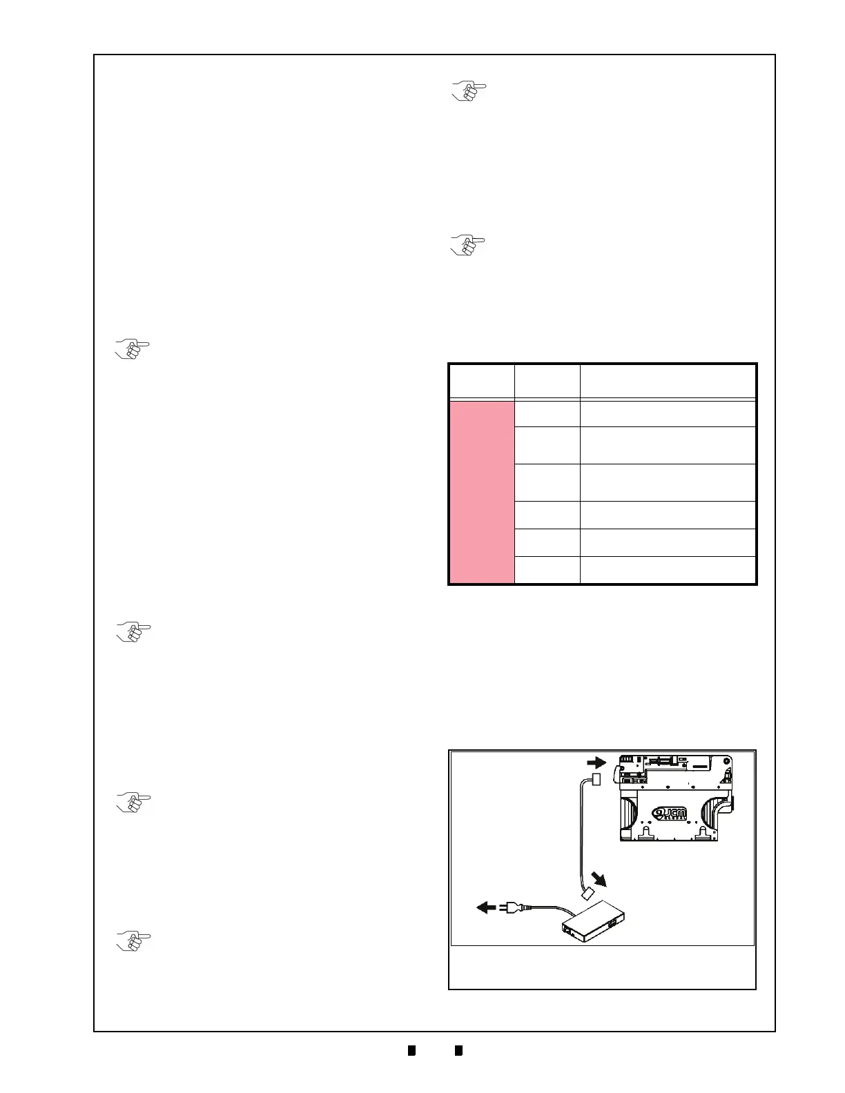
Figure 6-83 illustrates the VEGA Tool and Harness
Cable interconnections required to perform these
pro
cedures.
NOTE: While the adjustment process is
active, the Blue LED will momentarily flash
at high rate of speed.
NOTE: While the adjustment process is
active, the Front Panel LED will flash a
Purple Color at a high rate of speed.
NOTE: During the adjustment process, the
Front Panel LED will flash a Green Color at
a high rate of speed.
NOTE: While writing the data to EEPROM,
the Front Panel LED will flash a Yellow
Color at a high of rate speed.
Table 6-1 Red Blink Rate Error
LED Colors
Blink
Sequenc
e
Error Indication
Red
1 Blink
The Entrance Sensor adjustment has
failed.
2 Blinks
The Entrance Sensor adjustment
using White Reference Paper has
failed.
3 Blinks
The Validation Sensor adjustement
using Black Reference Paper has
failed.
4 Blinks
The Validation Sensor’s Non-Paper
adjustment has failed.
5 Blinks
The Edge Sensor adjustment has
failed.
6 Blinks
The EEPROM data writing process
has failed.
NOTE: If EEPROM data writing fails, all
previous adjustment data will be lost which
may disable performance of the VEGA
Unit!
NOTE: If the adjustment of ANY Sensor
fails, the Front Panel LED will blink RED.
If this error occurs, ensure that the
procedures were correctly performed, and
then re-perform them again. Refer to Table
6-1 for detail explanations of each RED
Color Blink sequence indication.
Figure 6-83 Tool and Harness Interconnections
Interface Connector
Power Supply
To A C Po w e r
c
a
b
Receptacle
a) VEGA Unit
b) Power Supply (e.g., UAC, MIB232, etc)
c) Harness

 Loading...


