P/N 960-100189RA_Rev. A {EDP #148850} © 2009, Japan CashMachine Co., Limited
Calibration and Testing VEGA™ Series BankNote Validator Section 6
3. Turn the VEGA Unit’s power ON.
4. Set DIP Switch Block DS1, Switch #1 to OFF.
When
the Feed Motor forward rotation test
begins, the Front Panel LED will extinguish
(goes out).
5. If the Feed Motor rotates
forward correctly, the
Front Panel LED Display will be extinguished
(dark) and forward rotation will continue.
6. To end the forward Feed Motor Test, turn the
VEGA Unit’
s power OFF, or set DIP Switch
Block DS1, Switch #1 to ON.
F
EED
M
OTOR
R
EVERSE
R
OTATION
T
EST
:
Perform the following steps to test the normal
reverse rotation functionality
of the Feed Motor:
1. Ensure that the VEGA Unit’s Power is OFF.
2. Set DIP Switch Block DS1, Switch #1 and #2
ON as
indicated in Table 6-2 for this test.
3. Turn the VEGA Unit’s power ON.
4. Set DIP Switch Block DS1, Switch #1 OFF.
When
the Feed Motor reverse rotation test
begins, the Front Panel LED will extinguish
(goes out).
5. If the Feed Motor rotates in reverse correctly, the
Front Panel LED
Display will be extinguished
(dark) and reverse rotation will continue.
6. To end the reverse Feed
Motor Test, turn the
VEGA Unit’s power OFF, or set DIP Switch
Block DS1, Switch #1 ON.
S
TACKER
M
OTOR
T
EST
Perform following step to test the Stacker Motor
rotation functionality:
1. Ensure that the VEGA Unit’s Power is OFF.
2. Set DIP Switch Block DS1, Switch #1 and #3
ON as
indicated in Table 6-2 for this test.
3. Turn the VEGA Unit’s power ON.
4. Set DIP Switch Block DS1, Switch #1 OFF.
When the S
tacker Motor test begins, the Front
Panel LED will extinguish (goes out).
5. If the Stacker Motor rotates forward/reverse
correctly, the Front Panel Display will be extin-
guished (dark), and the Motor will continue oper-
ating in a forward/reverse direction.
6. To finish the Stacker Mot
or Test, turn the VEGA
Unit’s power OFF, or set Set DIP Switch Block
DS1, Switch #1 ON.
A
GING
T
EST
The aging test repeatedly performs basic Validator
functions such as feeding, transporting and stack-
ing operations.
Perform following steps to repeate
dly test the
VEGA Unit’s basic feeding, transporting and
stacking functional performance:
1. Ensure that the VEGA Unit’s Power is OFF.
2. Set DIP Switch Block DS1, Switch #1, #2, & #4
to O
N as indicated in Table 6-2 for this test.
3. Turn the VEGA Unit’s power ON.
4. Set DIP Switch Block DS1, Switch #1 to OFF.
Wh
en the Aging test begins, the Front Panel LED
will extinguish (goes out).
5. If operation is normal, t
he Unit will perform the
following five (5) functions repetitively until the
test is stopped:
a) Feed Motor Reverse Rotation Test
b) Interval Test (20sec, LED lights White)
c) Feed Motor Forward Rotation Test
d) Stacking Test
e) Interval Test (20sec
, LED lights White).
6. To end the Aging Test, turn the VEGA Unit’s
power OFF, or set Set DIP Switch Block DS1,
Switch #1 ON.
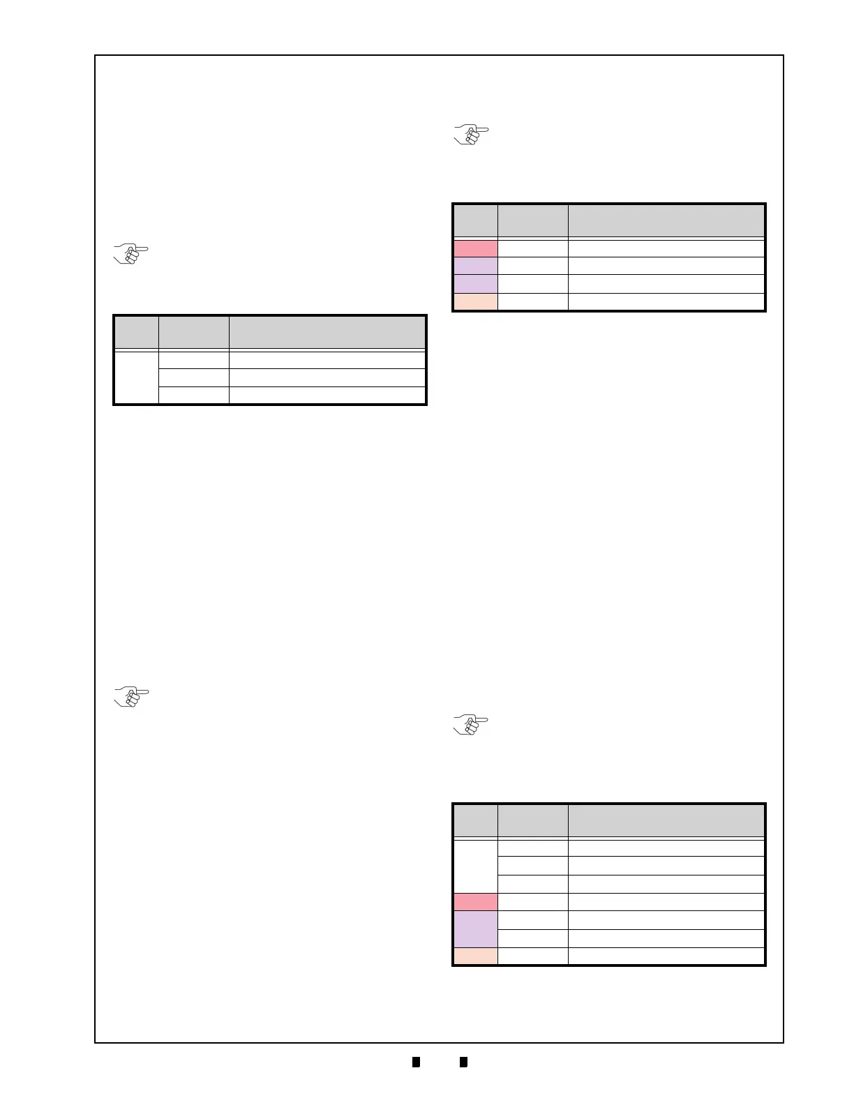
Table 6-3 Transport Motor Abnormal Error Codes
LED
Color
Blink
Sequence
Error Indication
White
3 Feed Motor Low Speed Problem
5 Feed Motor High Speed Problem
7 Feed Motor Lock-up Problem
NOTE: If the Front Panel LED blinks any
error sequence indicated in Table 6-3, the
Feed Motor forward rotation is abnormal.
NOTE: If the Front Panel LED blinks any
error sequence indicated in Table 6-3, the
Feed Motor reverse rotation is abnormal.
Table 6-4 Stacker Motor Abnormal Error Codes
LED
Color
Blink
Sequence
Error Indication
Red 5 Cash Box Seating Problem
Purple 5 Stacker Motor Lock-up
Purple 5 Stacker Motor Gear Problem
Orange 3 Stacker Full
Table 6-5 Feeding/Stacking Abnormal Error Codes
LED
Color
Blink
Sequence
Error Indication
White
3 Feed Motor Low Speed Problem
5 Feed Motor High Speed Problem
7
Feed Motor Lock-up
Red 5 Cash Box Seating Problem
Purple
5 Stacker Motor Lock-up
7
Stacker Motor Gear Problem
Orange 3 Stacker Full
NOTE: If the Front Panel LED blinks any
error sequence indicated in Table 6-4, the
Stacker Motor’s rotation is abnormal.
NOTE: If the Front Panel LED blinks any
error sequence indicated in Table 6-5, the
Feeding and/or Stacking function is
abnormal.

 Loading...


