P/N 960-100189RA_Rev. A {EDP #148850} © 2009, Japan CashMachine Co., Limited
VEGA™ Series
BankNote Validator
Section 2
2 INSTALLATION/OPERATION
This section provides installation and operation
instructions for the VEGA BankNote Validator.
The information within contains the following
features:
•
Installation
•
DIP Switch Configurations
•
Connector Pin Assignments
•
Preventive Maintenance
•
Retrieving Banknotes
•
Clearing Banknote Jam
•
Cleaning Procedure
•
Interface Schematic
•
Operational Flow Chart
Installation
Installation Procedure
Perform the following steps to install a VEGA
SH Unit:
1. Mount the VEGA in place without the Cash Box
installed.
2. Bolt the bottom of the VEGA
Frame into place
using four (4) M4 Hexnuts (See Figure 2-1 a
1
, a
2
,
a
3
& a
4
).
3. Set the VEGA DIP Switch
es to On-line Mode
(Refer to “DIP Switch Configurations” on page 2-
2 for Setting all DIP Switch conditions).
4. Connect the VEGA Unit to the Host Machine
using a
user supplied Harness (See Figure 2-2 a,
b, c, & d ).
5. Turn the VEGA Unit’s Power ON.
6. Activate the VEGA Unit normally
, and confirm
that the LED lighting sequence indicates an active
idle mode Color pattern as set by DIP Switch
selection (Refer to “DIP Switch Configurations”
on page 2-2 for Setting all DIP Switch condi-
tions).
Perform the following steps to install a VEGA
SU/SD Unit:
1. Set the VEGA DIP Switches to On-line Mode
(Refer to “DIP Switch Configurations” on page 2-
2 for Setting all DIP Switch conditions).
2. Connect the VEGA Unit to the Host Machine
using a
user supplied Harness (See Figure 2-2 a,
b, c, & d).
3. Turn the VEGA Unit’s Power ON.
4. Activate the VEGA Unit normally
, and confirm
that the LED lighting sequence indicates an activ
idle mode Color pattern as set by DIP Switch
Selection (Refer to “DIP Switch Configurations”
on page 2-2 for Setting all DIP Switch condi-
tions).
Figure 2-1 M4 Nut & DIP Switch Locations
NOTE: The bolt lengths are not to extend
more than 5mm up from the ground plane.
NOTE: Refer to Figure 2-1b) to locate the
3 DIP Switch Blocks inside the VEGA Unit.
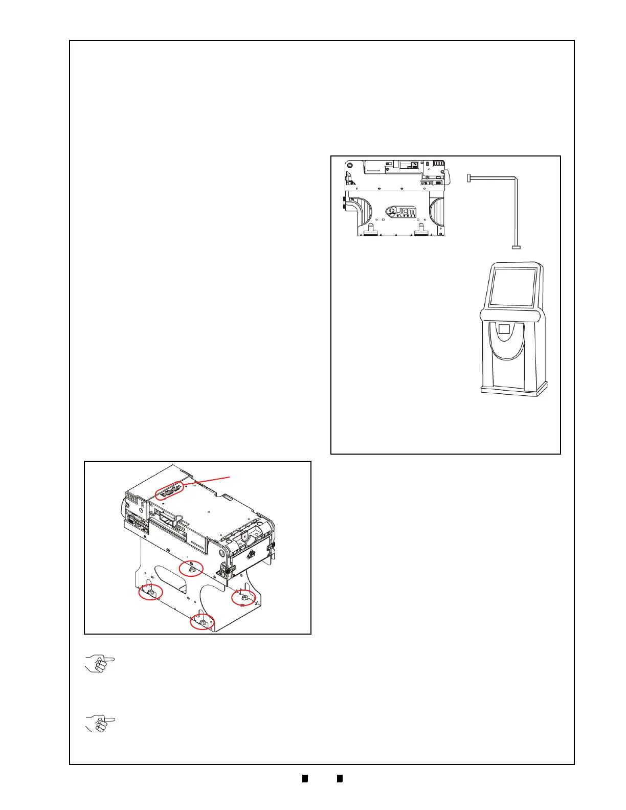
Figure 2-2 Cable Interconnection
b
c
a
d
a) VEGA Unit
b) VEGA Interface Connector
c) Harness (User prepared)
d) Host Machine (Game Machine, Juke Box, Kiosk,
etc.)

 Loading...


