P/N 960-100189RA_Rev. A {EDP #148850} © 2009, Japan CashMachine Co., Limited
Dissassembly/Reassembly VEGA™ Series BankNote Validator Section 4
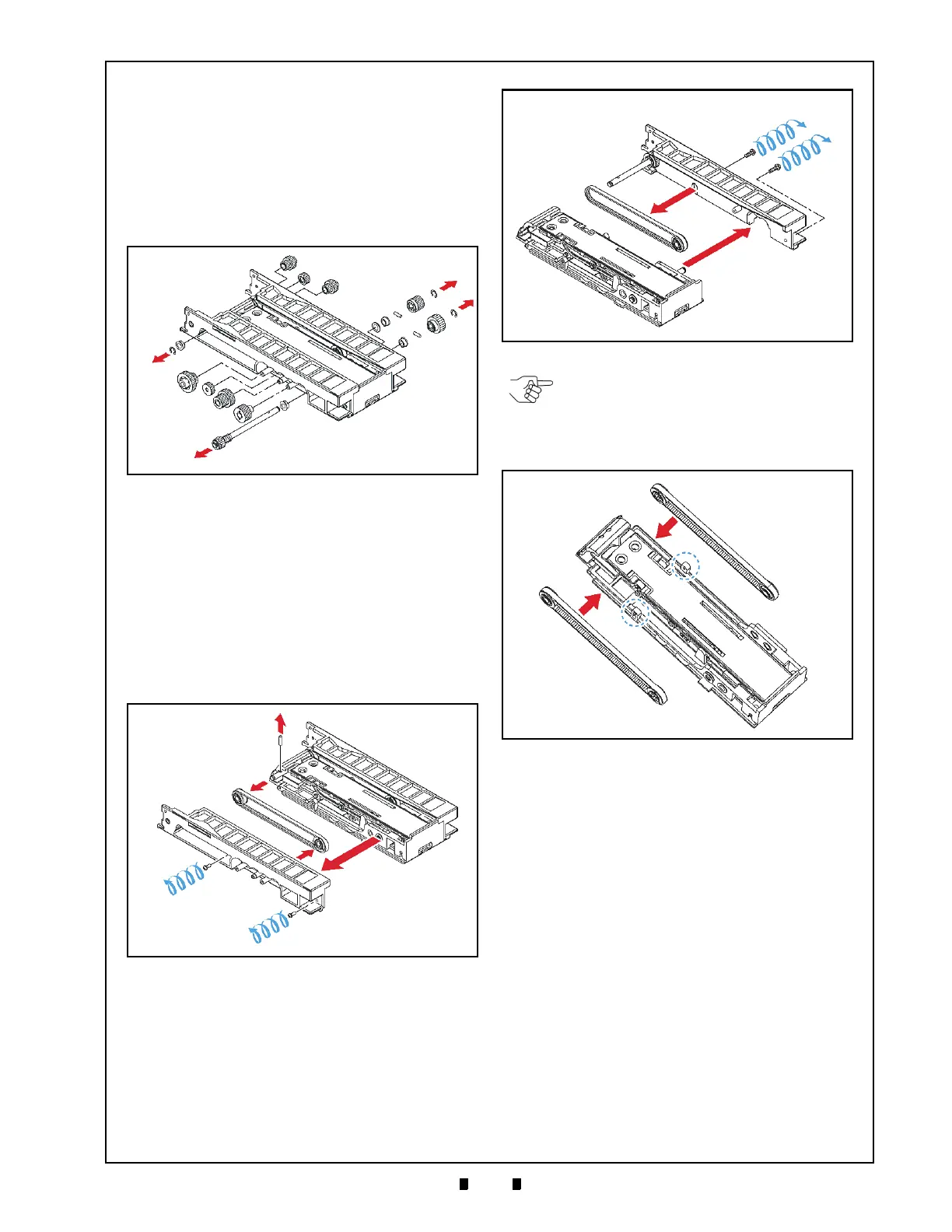
5. Remove the single E-Ring (See Figure 4-26 a)
from left end of the Stacker Unit Clutch Shaft.
6. Remove the two (2) E-Rings (See Figure 4-26 b
1
& b
2
), the two (2) Gears (See Figure 4-26 c
1
&
c
2
) and the two (2) Set Pins (See Figure 4-26 d
1
&
d
2
) located on the right side of the Stacker Unit
Assembly (See Figure 4-26 e).
7. Slide the Clutch Shaft (See Figure 4-26 f) out of
the Stacker Unit Assembly.
8. Remove the two (2) mounting screws (See Figure
4-27 a
1
& a
2
) retaining the Right Link Frame
(See Figure 4-27 b) to the center Ceiling Board
Assembly (See Figure 4-27 c), and separate the
Right Link Frame from the Ceiling Board
Assembly.
9. Remove the single Stacker Belt with its related
Pu
lleys (See Figure 4-27 d) from the right side of
the Right Link Frame.
10. Remove the single Set Pin (See Figure 4-27 e)
retaining the Shaft in the Ceiling Board
Assembly.
11. Remove the two (2) mounting screws (See Figure
4-28 a
1
& a
2
) retaining the Left Link Frame
(See Figure 4-28 b) to the center Ceiling Board
Assembly (See Figure 4-28 c), and separate the
Left Link Frame from
the Ceiling Board
Assembly.
12. Remove the single Stacker Belt (See Figure 4-28
d) located on the left side of the Le
ft Link Frame
(See Figure 4-28 c).
Figure 4-26 E-Ring, Gear & Clutch Shaft Removal
Figure 4-27 Right Stacker Belt Removal
Figure 4-28 Left Stacker Belt Removal
NOTE: Be careful not to damage the
Stacker Belts (See Figure 4-29 a
1
& a
2
) by
allowing them to rub on the Blue Dotted
Circled areas shown in Figure 4-29 when
reassembling the Ceiling Board Assembly.
Figure 4-29 Transport Belt Installation

 Loading...


