P/N 960-100189RA_Rev. A {EDP #148850} © 2009, Japan CashMachine Co., Limited
Section 6 VEGA™ Series BankNote Validator Calibration and Testing
O
FF
-
LINE
B
ANKNOTE
A
CCEPTANCE
T
EST
Perform following steps to test the VEGA Unit’s
Off-line Banknote Acceptance Test:
1. Ensure that the VEGA Unit’s Power is OFF.
2. Set DIP Switch Block DS1, Switch #1, #3, & #5
to ON
as indicated in Table 6-2 for this test.
3. Turn the VEGA Unit’s power ON.
4. Set DIP Switch Block DS1, Switch #1 to OFF.
When the O
ff-line Banknote Acceptance test
begins, the Front Panel LED will extinguish
(goes out).
Wait for the Front Panel LED Display to indicate
a
Stand-by Mode initialization blinking
sequence, and then insert Banknotes.
When the VEGA receives the Banknotes, the
Front
Panel LED will blink an Emerald Green
Color. The acceptable denominations are identi-
fied by the following Front Panel LED blink
sequence period
s:
5 Denomination Values = 1 Blink
10 Denomination Values = 2 Blinks
20 Denomination Values = 3 Blinks
50 Denomination Values = 4 Blinks
100 Denomination Values = 5 Blinks
Where the “Denomination Value” represents the
specific Country’
s Currency Type.
S
ENSOR
T
EST
Perform following steps to verify if the eight (8)
Sensors within the VEGA Unit are functional (i.e.,
the Entrance/Validation/Side Escrow/RC Flap/
Stacker & Box Sensors) when using the Paper and
Non-paper Calibration Procedures.
1. Ensure that the VEGA Unit’s Power is OFF.
2. Set DIP Switch Block DS1, Switch #1, #2, 3, #4
&
#5 to ON as indicated in Table 6-2 for this test.
3. Turn the VEGA Unit’s power ON.
4. Set DIP Switch Block DS1, Switch #1 to OFF.
The Fr
ont Panel LED will extinguish (goes out).
Sensor Confirmation will be Stand-by Mode.
5. Table 6-6 lists the DIP Switch Block DS2 setting
for the Sensor Test Configuration. Select the
intended
Sensor from the Table, and set DIP
Switch Block DS2 Switches according to the
Sensor Configuration Table.
6. When the selected Sensor detects
an object such
as a Banknote or a Test Paper, the Front Panel
LED Display will blink at a Yellow Color rate.
When there is no object detected, the Front Panel
LED Display will be extinguished.
NOTE: Between sequential Banknote
insertions, the Color of the Front Panel LED
Display will be determined by the Stand-by
Mode selections set by the user.
NOTE: If an error or a reject occurs, refer to
the Error and Reject Codes listed
in Appendix A of this Manual to identify the
cause of the malfunction.
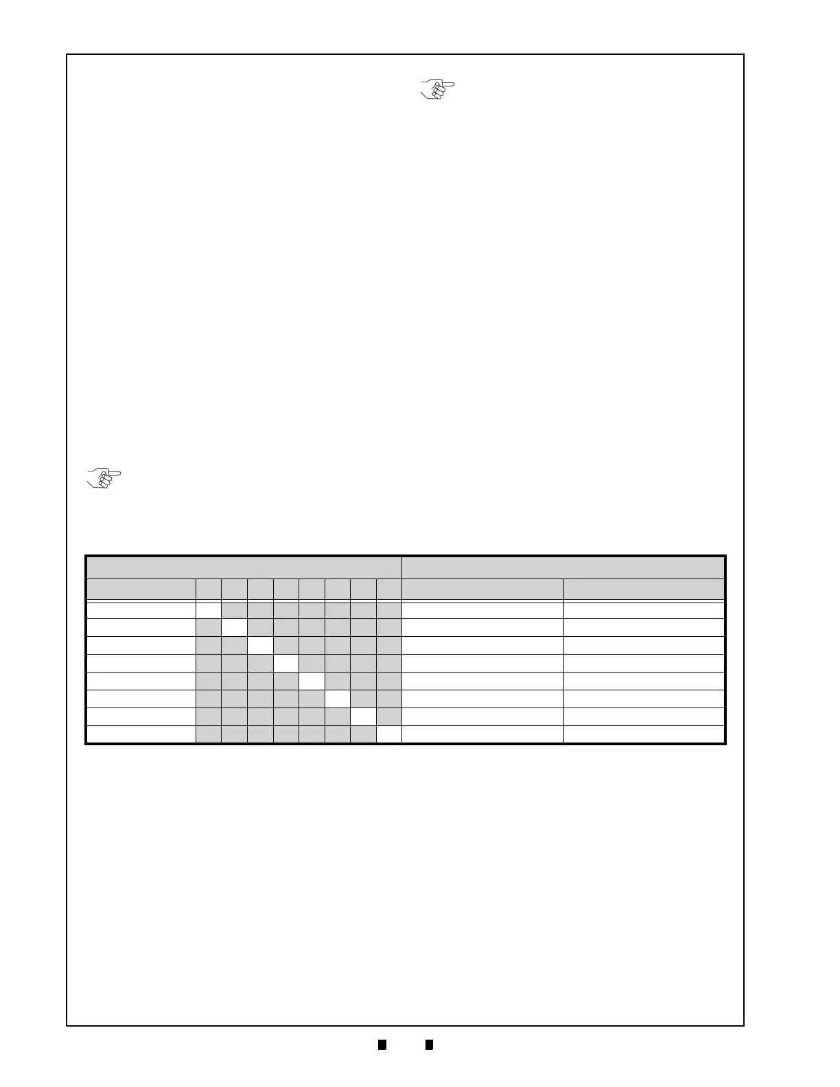
Table 6-6 DIP Switch Block DS2 Sensor Configuration Settings
DIP Switch Block DS2 Yellow LED State
Sensor 1 2 3 4 5 6 7 8 Lit Extinguished
Entrance Sensor ON OFF OFF OFF OFF OFF OFF OFF With Paper (Light Interception) No Paper (Transmissive)
Validation Sensor OFF ON OFF OFF OFF OFF OFF OFF With Paper (Light Interception) No Paper (Transmissive)
Side Sensor OFF OFF ON OFF OFF OFF OFF OFF With Paper (Light Interception) No Paper (Transmissive)
Escrow Sensor OFF OFF OFF ON OFF OFF OFF OFF With Paper (Light Interception) No Paper (Transmissive)
RC Flap Sensor OFF OFF OFF OFF ON OFF OFF OFF With Paper (Transmissive) No Paper (Light Interception)
Stacker Flap Sensor OFF OFF OFF OFF OFF ON OFF OFF With Paper (Transmissive) No Paper (Light Interception)
Stack-In Sensor OFF OFF OFF OFF OFF OFF ON OFF With Paper (Light Interception) No Paper (Transmissive)
Box Sensor OFF OFF OFF OFF OFF OFF OFF ON With Paper (Light Interception) No Paper (Transmissive)

 Loading...


