P/N 960-100189RA_Rev. A {EDP #148850} © 2009, Japan CashMachine Co., Limited
Appendix A VEGA™ SeriesBankNote Validator Troubleshooting
Error and Reject Codes
The flash rate is different between Error Codes and
Reject Codes. Long term blink rates (300msec)
indicate an Error Code situation, and a short term
flashing (120msec) condition indicates a Reject
Code situation.
These Error and Reject Code patterns also indicate
dif
ferently when On-line (e.g., communicating
with the Host Machine) versus Off-line (e.g., when
performing an Off-line Banknote Acceptance Test
during a Performance Test operation).
The user may be confused if the flashing patterns
are
complicated while On-line; so On-line Patterns
are made simpler than Off-line Patterns when
performing test functions.
However, Off-line Patterns can indicate more
complicated situations in order to ident
ify the
detailed cause of a specific error condition.
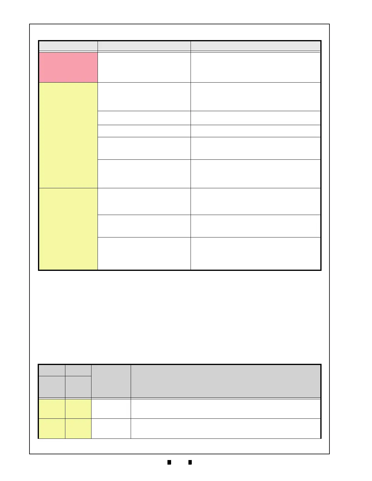
VEGA is not working
Banknote Jam occurs
(VEGA’s Bezel LED is
flas
hing red)
Unit setting malfunctioning.
Improper assembly and/or harness
connection.
Banknote Jam or poor condition occurs by
f
oreign object interference.
Check that Unit, Assembly, and Connections are properly set.
Check that there is not a Banknote Jam or foreign object
i
nterference inside the VEGA Unit. Check that the flashing
pattern is correct, and identify the indicated error by referring
to the Error Codes Table; then perform the necessary action
required (See Table A-2
).
Most Banknotes are
rejected
(VEGA’s Bezel LED is
fla
shing yellow)
Software not designed to accept current
banknotes.
Confirm that the acceptable denomination is correct by
referring
to the related Country’s Software Information Sheet.
Download the correct software.
(Refer to VEGA Service Manual for
details regarding proper
“Software Download” procedures).
DIP Switch settings are incorrect.
Check that the DIP Switch settings are properly set.
(See “DIP Switch Configurations” on page 2-2).
Banknote accept inhibit setting by command
fr
om the Host Machine.
Check that the command from the Host Machine is correct, and
change the setting to be acceptable for use with the VEGA Unit.
Dirt or foreign objects adhering to the
Sens
ors.
Clean the Sensors.
(See “Rotate the Cash Box Banknote Transportation Gear in the
necessary direction to remove the jammed Banknote
(See Figure 2-12).” on page 2-5 of this Service Manual).
Improper validation process performance.
Improper assembly and/or harness
connection.
The CPU board and/or the Sensors
m
alfunctioning.
Check that all assembly and connections are properly set.
Identify the error flashing pattern and identify the error by
r
eferring to the Error Codes Table; then perform the necessary
action required (See Table A-3
).
Validation rate is degraded
Some Banknotes are
r
ejected
(VEGA’s Bezel LED is
fla
shing yellow)
Software version is old.
Banknotes require proper d
enomination
from the Country’s Software.
Confirm that the required denomina
tion and/or issued year is
correct by referring to the Software Information Sheet.
(See “Rotate the Cash Box Banknote Transportation Gear in the
necessary direction to remove the jammed Banknote
(See Figure 2-12).” on page 2-5 of this Service Manual).
Dirt or foreign objects adhering to the
Sens
ors.
Clean the Sensors.
(See “Rotate the Cash Box Banknote Transportation Gear in the
necessary direction to remove the jammed Banknote
(See Figure 2-12).” on page 2-5).
Need calibration tests for the Sensors.
(Did not perform calibration tests after
dis
assembly or repair.)
Identify the error flashing pattern and locate the error by
r
eferring to the Error Codes Table; then perform the necessary
action required
Perform calibration tests if necessary.
(Refer to VEGA Service Manual for the detail of “Calibration and
T
esting”).
Table A-1 LED Diagnostics (Continued)
Symptoms Causes Solutions
Table A-2 Error Codes
on-line off-line
Error Causes and Solutions
Color
Flashes
(msec)
Color
Flashes
(msec)
Yellow
1
(300)
Yellow
1
(300)
ROM Error
ROM (Software) is malfunctioning.
[Solution] Re-download the current software. If the error is not corrected by this operation,
change the CPU Board.
Yellow
2
(300)
Yellow
2
(300)
RAM Error
RAM is malfunctioning.
[Solution] Change the CPU Board.

 Loading...


