P/N 960-100189RA_Rev. A {EDP #148850} © 2009, Japan CashMachine Co., Limited
Section 6 VEGA™ Series BankNote Validator Calibration and Testing
Calibration Using a PC
The following two (2) ways to calibrate a VEGA
Unit using a PC exist:
1. Calibration by writing a Serial Number into the
Unit, and
2. Calibration without writing a Serial Number into
the Un
it.
Refer to Figure 6-15 for details concerning Tool
requirements and Harness connections required to
perform this
procedure.
Before proceeding with this procedure, copy the
Adj
ustment Programs (i.e.,
VEGA_Adjustment.exe
and VEGA_Adjustment_Zero.exe) into the PC
([C:\
VEGA])
Folder.
VEGA_A
DJUSTEMENT
.
EXE
P
ROGRAM
U
SE
To use the
VEGA_Adjustment.exe
Program, pro-
ceed as follows:
1. Turn the VEGA Unit’s power OFF.
2. Set DIP Switch Block No. 1, Switches #1, #2, #3
&
#5 ON (See Figure 6-21).
3. When turning the VEGA Power Switch ON, the
Front
Panel LED will slowly blink at a Green
Color rate.
4. Set DIP Switch Block No. 1, Switch #1 OFF. The
Front
Panel LED will begin to blink in a Cyan,
White, and Blue Color sequence.
5. Launch the (
VEGA_Adjustment.exe
) calibration
Program. The window shown in Figure 6-22 will
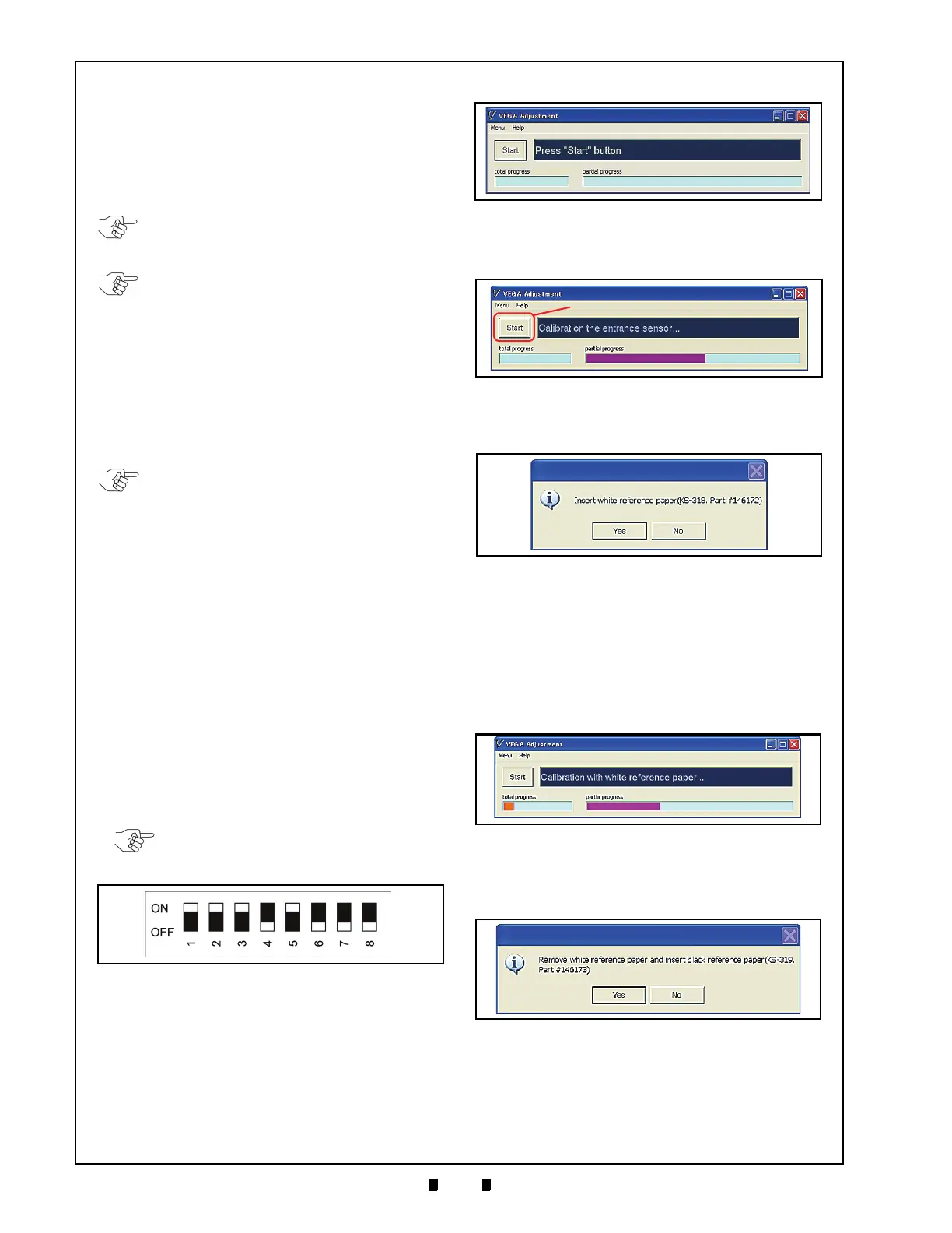
appear when the application is active.
6.
7. Mouse-click on the “
Start
” Screen Button to
begin the Entrance Sensor’s adjustment
procedure (See Figure 6-23 a).
8. When the Entrance Sensor’s Adjustment is com-
plete, the White Reference Paper Setting window
show
n in Figure 6-24 will appear.
9. Set the White Reference Paper in place when the
Screen show
n in Figure 6-24 on page 6-6
appears.
See Reference Paper Usage
on page 6-
5 of this Section).
10. When the White Reference Paper is set in place,
Mo
use-click on the “
Yes
” Screen Button. This
action performs the White Reference Paper
adjustment procedure (See Figure 6-25).
11. Once the White Reference Paper adjustment
procedure is complete, the message screen shown
in
Figure 6-26 will appear.
12. Remove the White Reference Paper from the
T
ransport Section. To remove the White Refer-
ence Paper, reverse the paper loading procedure
NOTE: Serial No. of the VEGA is factory
installed. Use
VEGA_Adjustment.exe
Program
for normal adjustment performance.
NOTE: Perform the PC Serial Number
writing calibration procedure using the
VEGA_Adjustment_Zero.exe
Program
whenever replacing or removing the VEGA
CPU Board! The CPU Board contains a
unique Serial Number, so its data identity to
related files disappears when the CPU
Board is replaced. This condition may cause
performance of the VEGA to stop,
depending on the related Interfaces set to
operate with the particular VEGA Unit.
NOTE: The
VEGA_Adjustment_Zero .exe
Program can be used for performing
calibration and additional functions
following; Serial No. Writing, Stand-by LED
Pattern Color Setting, and Clearing
EEPROM.
NOTE: DIP Switch Block No.2 and No. 3
settings are not required for this Software
Installation.
Figure 6-21 DIP Switch Block #1 Initial Settings
Figure 6-22 VEGA Adjustment File Screen
Figure 6-23 Entrance Sensors Adjustment
Figure 6-24 White Reference Paper Placement
Request Screen
Figure 6-25 White Reference Paper Calibration
Progress Screen
Figure 6-26 Black Reference Paper Placement
Request Screen

 Loading...


