P/N 960-100189RA_Rev. A {EDP #148850} © 2009, Japan CashMachine Co., Limited
Section 4 VEGA™ Series BankNote Validator Dissassembly/Reassembly
7. Unplug the two (2) Signal Connectors from the
CPU Board (See Figure 4-3 c) on the opened
Upper Assembly (See Figure 4-3 a).
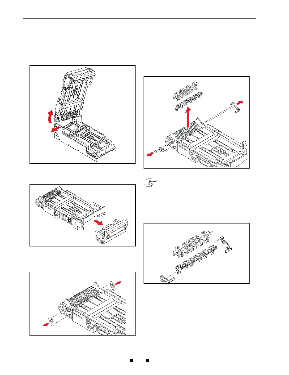
8. While lifting up on the Upper Assembly
(See Figure 4-4 a), gently widen one side of the
lower Transport Section hinge area (See Figure 4-
4 b), and separate the Upper Assembly from the
lower Transport Section (See Figure 4-4 b).
9. Pull the Front Bezel (See Figure 4-5 a) forward
and off the Upper Assembly (See Figure 4-5 b).
10. Remove the two (2) Flap Positioning Springs
(See Figure 4-6 a
1
& a
2
) from the side of the
Upper Assembly (See Figure 4-6 b).
11. Remove the single E-Ring (See Figure 4-7 a)
from the end of the hinge assembly’s Shaft
(See Figure 4-7 b).
12. Side the shaft containing
the mounted left Flap
Return Lever Arm, our of the Upper Assembly
(See Figure 4-7 c), and remove the right Flap
Lever Arm from the shaft end (See Figure 4-7 d).
13. Carefully remove Flap #a (See Figure 4-7 f) and
Flap #2 (See Figure 4-7 g) up and off the Upper
Assembly.
14. Carefully press-in, and i
ndividually pull upward
on the six (6) Plastic Retaining Tabs one at a time
on the Upper Transport Assembly (See Figure 4-9
a
1
through a
6
), and carefully remove the Upper
Transport Assembly (See Figure 4-9 b) up and off
the Lower Transport Assembly Frame
(See Figure 4-9 c).
Figure 4-4 Upper Assembly Separation (Part 2)
Figure 4-5 Front Bezel Removal
Figure 4-6 Flap Positioning Spring Removals
Figure 4-7 Shaft and Flap #1 & #2 Removal
NOTE: When re-attaching the Right Flap
Lever Arm, ensure that the retaining pin
portion of the left Flap Lever Arm
(See Figure 4-8 a) securely fits into the
Flap #1 mating hole (See Figure 4-8 b),
and the corresponding pin of the right Flap
Lever Arm (See Figure 4-8 c) fits into its
Flap #2 mating hole (See Figure 4-8 d).
Figure 4-8 Flap Lever Arm Reassembly

 Loading...


