P/N 960-100189RA_Rev. A {EDP #148850} © 2009, Japan CashMachine Co., Limited
Section 6 VEGA™ Series BankNote Validator Calibration and Testing
3. When turning the VEGA Power Switch ON, the
Front Panel LED will slowly blink at a Green
Color rate.
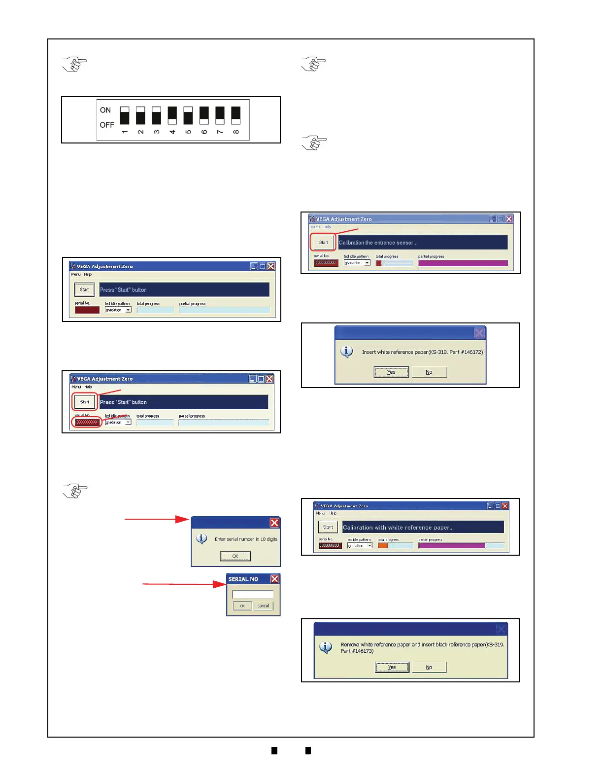
4. Set DIP Switch Block No. 1, Switch #1 OFF. The
Front
Panel LED will begin to blink in a Cyan,
White, and Blue Color sequence.
5. Launch the (
VEGA_Adjustment _Zero.exe
) cal-
ibration Program. The window shown in Figure
6-37 will appear when the application is active.
6. Mouse-click on the “
serial No.
” Text Entry Field
(See Figure 6-38 a) located just below the “
Start
”
Screen Button (See Figure 6-38 b).
7. Type in the new VEGA Serial Number as a One-
byte
Character, and then Mouse-click on the
“
Start
” Screen Button (See Figure 6-38 b).
8. Set the Stand-by Mode F
ront Panel LED Display
Color pattern by choosing the desired pattern
from the three (3) selections available from the
“
led idle pattern
” Pull-down Menu. The Three (3)
choices are “Rainbow” Gradation, Green or
Blue.
9. Mouse-click on the “
Start
” Screen Button to
begin the Entrance Sensor’s adjustment
procedure (See Figure 6-39 a).
10. When the Entrance Sensor’s Adjustment is com-
plete, the White Reference Paper Setting window
show
n in Figure 6-40 will appear.
11. Set the White Reference Paper in place when the
Screen show
n in Figure 6-40 on page 6-8
appears.
See Reference Paper Usage
on page 6-
5 of this Section).
12. When the White Reference Paper is set in place,
Mo
use-click on the “
Yes
” Screen Button. This
action performs the White Reference Paper
adjustment procedure (See Figure 6-41)
13. Once the White Reference Paper adjustment
procedure is complete, the “Remove…
”
message
Screen shown in Figure 6-42 will appear.
NOTE: DIP Switch Block No.2 and No. 3
settings are not required for this Software
Installation.
Figure 6-36 DIP Switch Block #1 Initial Settings
Figure 6-37 VEGA Adjustment Zero File Screen
Figure 6-38 Serial No. Input Field Location
NOTE: If the “Start” Screen Button is clicked
before a Serial Number is input, the Dialog
Message Screen indicated at right will
appear.
Mouse-click on the
Dialog’s “OK” Screen
Button, and the
“SERIAL NO.” Text
Input Dialog Screen at right
will appear.
Type the required VEGA
Serial No. into the Text Entry
Field, and then click its “ok”
Screen Button.
NOTE: The stand-by indication can also be
set by following the DIP Switch
Configurations procedure located on
page 2-2 of Section 2 this Manual.
The Last saved setting of either procedure
is always reflected as the current Front
Panel LED Stand-by indication.
NOTE: Unless a complete Set-up Mode
Color selection result is saved in EEPROM,
the VEGA Unit will be unable to decide its
Stand-by Color selection.
Figure 6-39 Entrance Sensors Adjustment
Figure 6-40 White Reference Paper Placement
Request Screen
Figure 6-41 White Reference Paper Calibration
Progress Screen
Figure 6-42 Black Reference Paper Placement
Request Screen

 Loading...


