P/N 960-100189RA_Rev. A {EDP #148850} © 2009, Japan CashMachine Co., Limited
Section 6 VEGA™ Series BankNote Validator Calibration and Testing
Driver Installation Procedure
Perform the following steps to install the various
VEGA Software Drivers (Refer to Figure 6-2 for
the Tool Requirements and Harness Connector
locations). Befor
e downloading the VEGA Soft-
ware package, the VEGA USB Driver (e.g., usb-
ser.sys & usbvega.inf) must be installed in a
de
signated Folder on the PC first as follows:
1. Create a VEGA Folder on the “C” Drive (e.g.,
C:\VEGA), and copy the VEGA USB
Drivers (usbser.sys & usbvega.inf) into the PC
Folder created.
2. Connect the USB Cable to the VEGA Unit.
3. Supply power to the VEGA Unit.
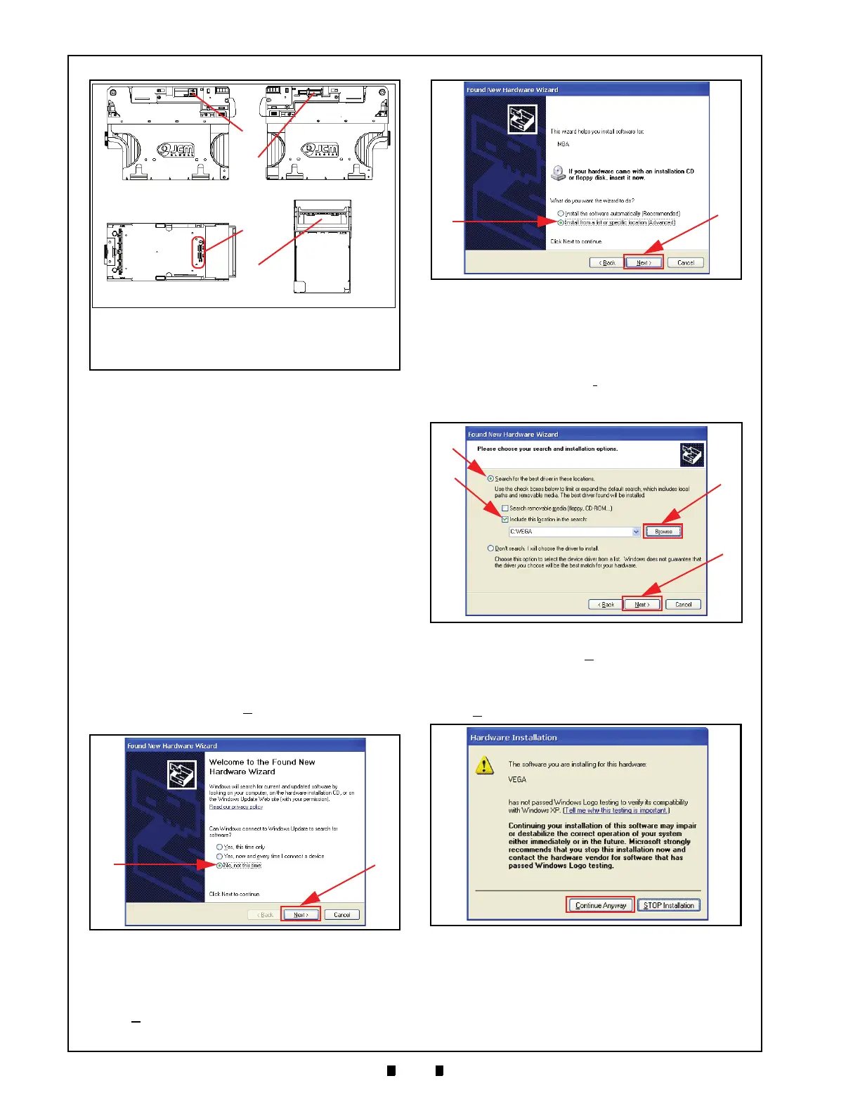
4. The “
Found New Hardware Wizard
” Screen
shown in Figure 6-4 should appear. Mouse-click
on the Radio Screen Button located beside “
No,
not this time
” (See Figure 6-4 a), and then
Mouse-click on the “
Next>
” Screen Button
(See Figure 6-4 b).
5. On the next screen that appears, Mouse-click
on
the Radio Screen Button located next to “
Install
from a list or specific location (Advanced)
”
(See Figure 6-5 a), and then Mouse-click on the
“
Next>
” Screen Button again (See Figure 6-5 b).
6. Mouse-click on the Radio Screen Button located
next to “
Search for the best driver in these
locations.
” (See Figure 6-6 a) and Mouse-check
the “
Include this location in the search:
” Check-
box (See Figure 6-6 b).
7. Mouse-click on the “
Browse
” Screen Button
(See Figure 6-6 c) and select the new VEGA
Folder [C:\VEGA] recently
created on the PC.
8. Mouse-click on the “
Next>
” Screen Button
(See Figure 6-6 d) to display the next screen. The
“
Hardware Installation
” Message Screen shown
in Figure 6-7 will appear. Mouse-click select the
“
Continue Anyway
” Screen Button to continue.
9. When software installation is complete, the
“
Completing the Found New Hardware
Wizard
” Screen shown in Figure 6-8 will appear.
10. Mouse-click on the “
Finish
” Screen Button to
close the Screen.
Figure 6-3 VEGA Port, DIP Switch & LED
Indicator Locations
Left Side Right Side
Top Surface
Front Side
a
b
c
d
a) USB Port
b) Interface Connector Receptacle
c) Mini-DIP Switch Blocks (3)
d) LED Indicator Location (Banknote Insertion Slot)
Figure 6-4 Hardware Wizard Welcome Screen
Figure 6-5 Installation Path Selection Screen
Figure 6-6 Install Options Screen
Figure 6-7 Installation Warning Screen

 Loading...


