P/N 960-100189RA_Rev. A {EDP #148850} © 2009, Japan CashMachine Co., Limited
Calibration and Testing VEGA™ Series BankNote Validator Section 6
14. Remove the White Reference Paper from the
Transport Section. To remove the White Refer-
ence Paper, reverse the paper loading procedure
described in
Reference Paper Usage
on page 6-
5 of this Section.
15. Set the Black Reference Paper in place (
See
Reference Paper Usage
on page 6-5 of this
Section).
16. When the Black Reference Paper is set in place,
Mouse-click on the
“
Yes
” Screen Button to
begin the Black Reference Paper adjustment
procedure (See Figure 6-43).
17. Once the Black Reference Paper adjustment
procedure is complete, the Message Screen
shown
in Figure 6-44 will appear.
18. Remove the Black Reference Paper. To remove
the Black
Reference Paper, following reverse
procedure for loading the paper. (
See Reference
Paper Usage
on page 6-5 of this Section).
19. Once the Black Reference Paper is removed,
Mouse-click on the
“
Yes
” Screen Button
(See Figure 6-45) to begin the Non-Paper adjust-
ment procedure.
20. Once the Non-paper adjustment procedure is
complete, the Motor Speed Te
st program will
automatically begin and test progress will appear
as shown by the Figure 6-47a Barographs.
.
21. Once the Motor Speed Test is complete, the
message screen shown in Figure 6-48 will appear.
22. Mouse-click on the “
Yes
” Screen Button to begin
writing the calibration results into the VEGA
Unit’s EEPROM (See Figure 6-49).
23. As the calibration result data is being written into
EEPRO
M, the progress Barographs shown in
Figure 6-50a will be active.
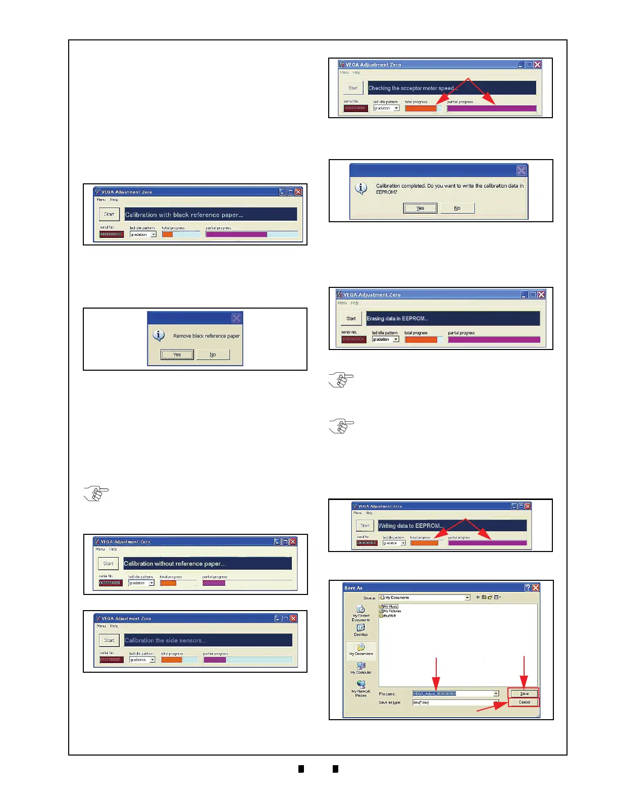
Figure 6-43 Black Reference Paper Calibration
Progress Screen
Figure 6-44 Black Reference Paper Removal
Request Screen
NOTE: Figure 6-42 will appear for Non-
paper Calibration of the Validation Sensors,
and then Figure 6-33 for will appear for
Non-paper Calibration of the Edge Sensors.
Figure 6-45 Non-Paper Calibration Screen 1
Figure 6-46 Non-Paper Calibration Screen 2
Figure 6-47 Motor Speed Test
Figure 6-48 Adjustment Complete; Request
Writing Data To Memory Screen
Figure 6-49 Clearing EEPROM Data Screen
NOTE: Clearing data in the EEPROM takes
approximately 40 seconds. While data is
clearing, the Front Panel LED will blink at a
Ye ll ow Color rate.
NOTE: When clearing data out of the
EEPROM fails, and the message “Erasing
data EEPROM failed”, appears, the CPU
Board needs to be replaced.
Figure 6-50 Writing EEPROM Data Progress
Screen
Figure 6-51 “Save As” PC Screen

 Loading...


