P/N 960-100189RA_Rev. A {EDP #148850} © 2009, Japan CashMachine Co., Limited
Section 4 VEGA™ Series BankNote Validator Dissassembly/Reassembly
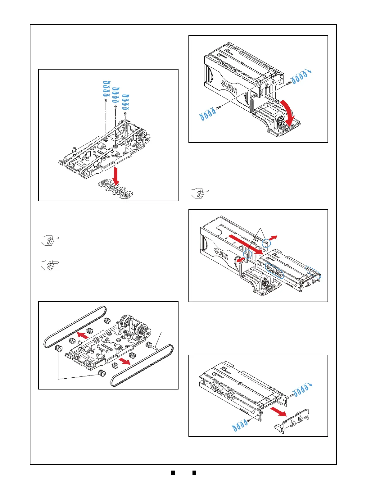
2. Remove the three (3) screws (See Figure 4-21 a
1
to a
3
) retaining the Belt Cover Assembly to the
Base Carrier Unit (See Figure 4-21 b).
3. Remove the Belt Cover Assembly from the Base
Carr
ier Unit (See Figure 4-21 c).
4. Remove the two (2) Transport Belts (See Figure
4-22 a
1
& a
3
) from the Base Carrier Unit Assem-
bly (See Figure 4-22 b).
Stacker Belt Removal
To remove the VEGA Unit’s Stacker Belts,
proceed as follows:
1. Open the Stacker Box Cover (See Figure 4-23 a),
and remove the two (2) internal Stacker Unit
Assembly mounting screws located inside the
Stacker Box (See Figure 4-23 b
1
& b
2
).
2. Carefully spread both upper sides of
the Stacker
Box Assembly apart (See Figure 4-24 a) and
gently pull the Stacker Unit Assembly forward
(See Figure 4-24 b) out of the Stacker Box Frame
(See Figure 4-24 c).
3. Remove the two (2) Course Path Reversing Guide
Mou
nting Screws (See Figure 4-25 a
1
& a
2
)
located on each side of the Stacker Unit Assembly
(See Figure 4-25 b).
4. Pull the Course Path Reversing Guide off of the
S
tacker Unit Assembly (See Figure 4-25 c).
Figure 4-21 Belt Cover Removal
NOTE: Be careful not to loose the eight (8)
Pulley Pins (See Figure 4-22 c) when
removing the two Transport Belts.
NOTE: The two (2) End Pulleys located on
each side of the Base Carrier Unit
(See Figure 4-22 d) are a different shape
from the other Pulleys. Be sure to replace
them in their correct locations when
reassembling the Unit.
Figure 4-22 Transport Belt Removals
Figure 4-23 Stacker Unit Removal (Part 1)
NOTE: Be careful not to loose the seven
(7) Drive Gears (See Figure 4-24 d) from
the Stacker Unit during its removal.
Figure 4-24 Stacker Unit Removal (Part 2)
Figure 4-25 Course Path Reversing Guide
Removal

 Loading...


