P/N 960-100189RA_Rev. A {EDP #148850} © 2009, Japan CashMachine Co., Limited
Section 2 VEGA™ Series BankNote Validator Installation/Operation
5. Turn the VEGA Unit’s Power OFF and discon-
nect the Harness between the VAGA and the Host
Machine.
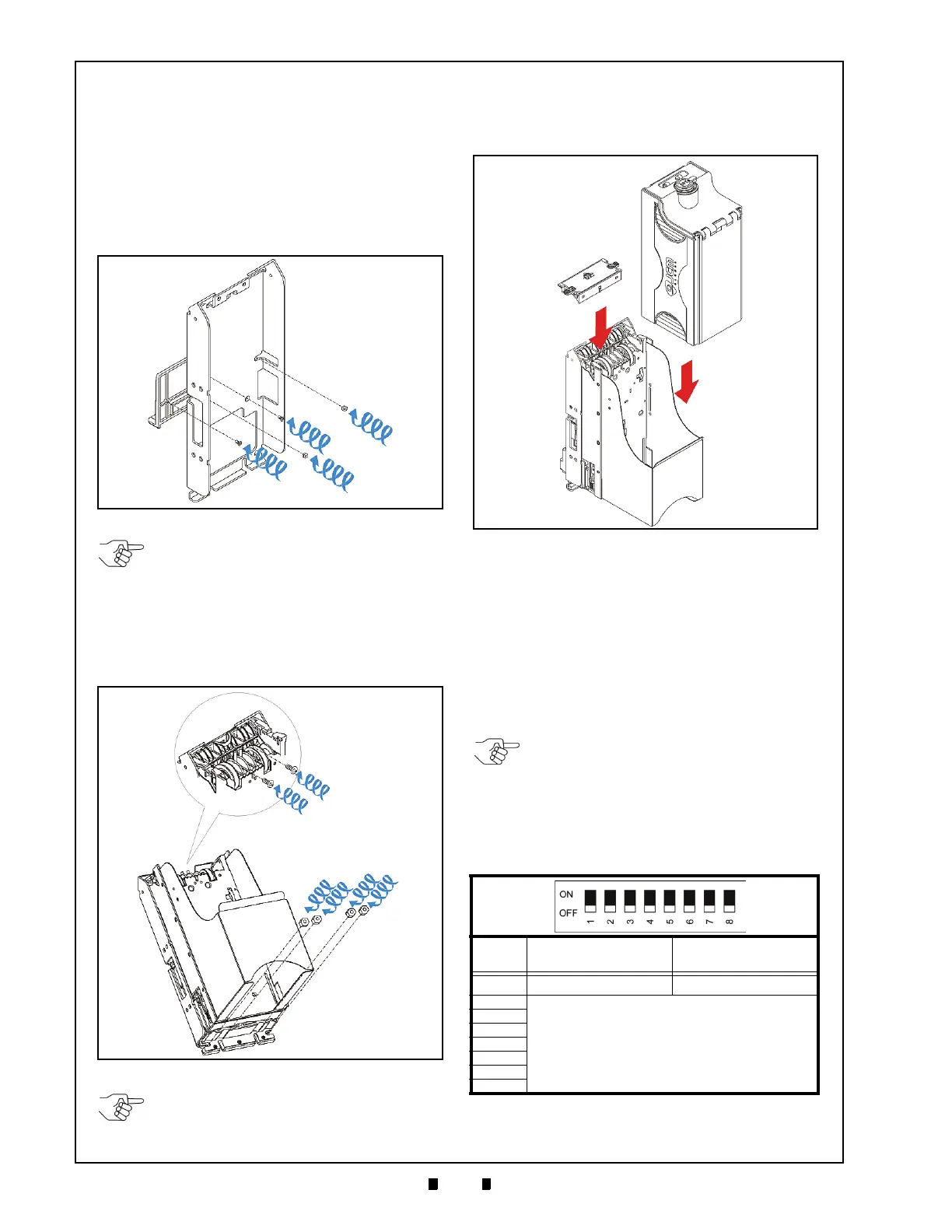
6. Connect the attached Bezel2 Plate (See Figure 2-
3 a) on the VEGA SD/SU Braket (See Figure 2-3
b) using two (2) M4 Screws (See Figure 2-3 c
1
&
c
2
).
7. Mount the VEGA SD/SU B
raket into place of the
Host Machine using two (2) M4 Hexnuts
(See Figure 2-3 d
1
& d
2
).
8. Bolt the VEGA SD/SU Unit into the VEGA SD/
SU
Braket installed on the Host Machine using
two (2) M4 Screws (See Figure 2-4 a
1
& a
2
) and
two (2) or four (4) M4 Hexnuts (See Figure 2-4
b
1
, b
2
, b
3
& b
4
).
9. Seat the Cash Box (See Figure 2-5 a) into the
Flame and put the Course Path Reversing Guide
Cover (See Figure 2-5 b) on the Upper Section.
10. Turn the VEGA Unit’s Power ON.
DIP Switch Configurations
This portion provides the basic and special DIP
Switch settings for the VEGA Unit.
Basic Settings
To activate the ID-003 Interface or the ccTalk
Interface, set DIP Switch Block DS2 Switches #6
th
rough #8 to ON. Then set DIP Switch Block DS1
Switches #2 through #8 ON.
Refer to the related Country’
s Software Information
Sheet for further Switch setting details.
Figure 2-3 Bezel Attachment
NOTE: The bolt lengths are not to extend
more than 15mm up from the Host
Machine base.
Figure 2-4 M4 Screw & Nut Locations
NOTE: The number of screws depend on
each Host Machine specification.
Table 2-1 DIP Switch Block 1 Settings
Switch
No.
Switch ON Switch OFF
1
Test Mode Basic Performance
2
Refer to the Related Country’s Software
Specification Sheet
3
4
5
6
7
8
Figure 2-5 Cash Box & Guide Cover Location
NOTE: The setting of Switches #2 through
#8 on DS1, and Switches #1 through #5 on
DS2 are decided by a Specific Country’s
Software (See Table 2-1 and Table 2-2).

 Loading...


