P/N 960-100189RA_Rev. A {EDP #148850} © 2009, Japan CashMachine Co., Limited
Section 4 VEGA™ Series BankNote Validator Dissassembly/Reassembly
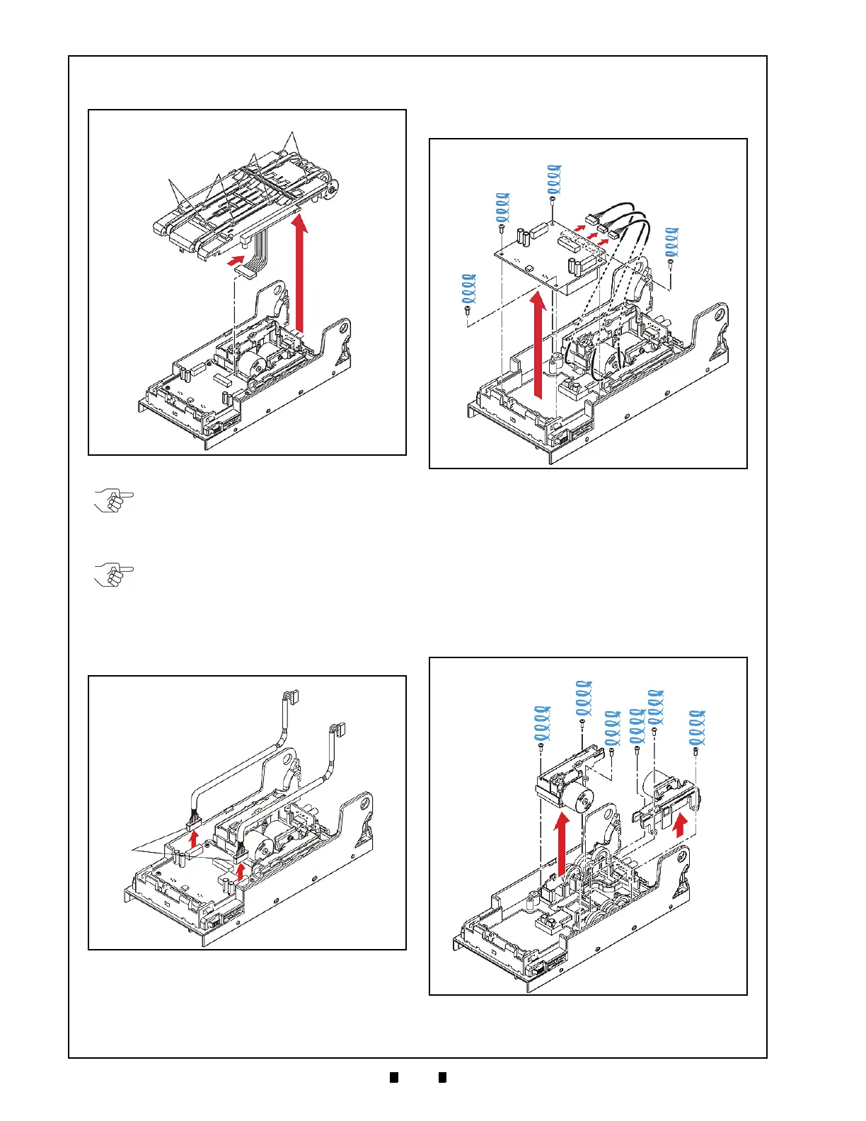
3. Lift the Base Carrier Unit (See Figure 4-13 c) up
and off the Lower Transport Assembly.
4. Unplug the two (2) Inter-Assembly Harnesses
(See Figure 4-14 a) from the Sub-Circuit Board.
5. Remove the four (4) Sub-Circuit Board Mounting
Scr
ews (See Figure 4-15 a
1
through a
3
) and
unplug the three (3) Connectors (See Figure 4-15
b) located on the back side of the
Sub-
Circuit Board (See Figure 4-15 c).
6. Lift the Sub-Circuit Board up and off the Lower
T
ransport Assembly (See Figure 4-15 d).
Feed and Stacker Motor Removal
To remove the VEGA Unit’s Feed and Stacker
Motors, proceed as follows:
1. Remove the three (3) mounting screws
(See Figure 4-16 a
1
to a
3
) retaining the Transport
Gear Box Sub-assembly (See Figure 4-16 b) to
the Lower Transport Assembly (See Figure 4-16
c), and lift the Transport Gear Box Sub-assembly
up and of
f the Lower Transport Assembly.
Figure 4-13 Base Unit Carrier Removal (Part 2)
NOTE: Be careful that the six (6) left and
right side Pulleys do not fall out of the
Assembly (See Figure 4-13 d
1
through d
3
)
when removing the Base Carrier Unit.
NOTE: Ensure that Harness replacement
during re-assembly (See Figure 4-13 e)
does not disturb the Transport Belt
positions (See Figure 4-13 f) when
reassembling the Base Carrier Unit.
Figure 4-14 Unplug Inter-Assembly Harnesses
Figure 4-15 Sub-Circuit Board Removal
Figure 4-16 Gear Box Motor Assembly Removals

 Loading...


