System SourceMeter® Instrument Reference Manual Section 2: General op
2600BS-901-01 Rev. C / August 2016 2-103
GPIB standards
The GPIB is the IEEE-488 instrumentation data bus, which uses hardware and programming
standards originally adopted by the Institute of Electrical and Electronic Engineers (IEEE) in 1975.
The instrument is IEEE Std 488.1 compliant and supports IEEE Std 488.2 common commands and
status model topology.
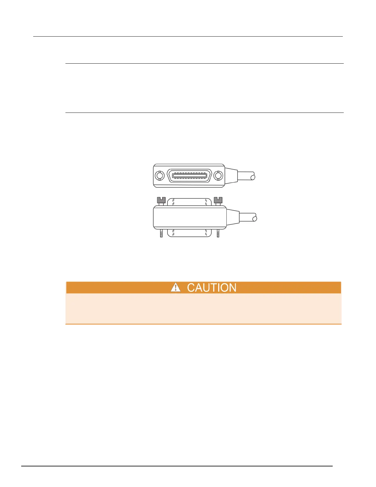
Connect the GPIB cable
To connect an instrument to the GPIB bus, use a cable equipped with standard IEEE-488 connectors,
as shown below.
Figure 48: GPIB connector
To allow many parallel connections to one instrument, stack the connectors. Each connector has two
screws to ensure that connections remain secure. The figure below shows a typical connection
diagram for a test system with multiple instruments.
To avoid possible mechanical damage, stack no more than three connectors on any one instrument.
To minimize interference caused by electromagnetic radiation, use only shielded IEEE-488 cables.
Contact Keithley Instruments for shielded cables.
To connect the instrument to the IEEE-488 bus, line up the cable connector with the connector on the
rear panel. Install and tighten the screws securely, making sure not to overtighten them. The following
figure shows the location of the connector.Connect any additional connectors from other instruments
as required for your application. Make sure the other end of the cable is properly connected to the
controller. You can only have 15 devices connected to an IEEE-488 bus, including the controller. The
maximum cable length is either two meters (6.5 feet) multiplied by the number of devices or 20
meters (65.6 feet), whichever is less. Erratic bus operation may occur if you ignore these limits.

 Loading...


