Thereafter, you can start and stop tag data links for the entire network or individual devices from the
Network Configurator
. Starting and stopping tag data links for individual devices must be performed for
the originator.
Furthermore, you can use system-defined variables to start and stop the entire network. Refer to
7-2-12 Starting and Stopping Tag Data Links on page 7-68 for details.
7-1-6
Controller Status
You can include the Controller status as a member of a tag set in the data sent and received.
The Controller status is a set of flags that indicate the operating status of the CPU Unit (operating in-
formation, error information, Controller error level).
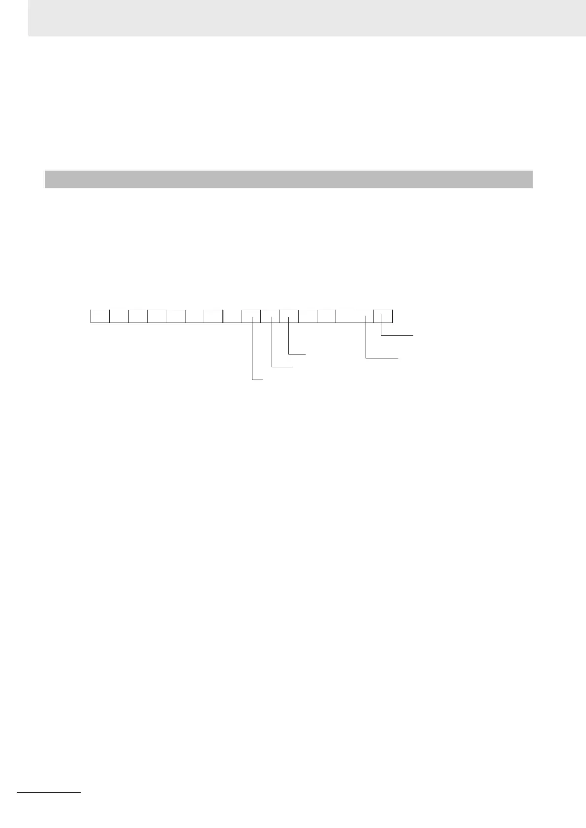
If the Controller status is specified as an output (send) tag, the Controller status is added to the start of
the tag set in the following format.
(Select the Include Option for Controller Status in the upper right of the Edit T
ag Set Dialog Box.)
15 14 13 12 11 10 9 8 7 6 5 4 3 2 1 0
0 0 0 0 0 0 0 0 0 0 0
Major fa
ult level
Controller error
Partial fault level Controller error
Minor fault level
Controller error
Controller Error Flag
Controller Operating Flag
Note Of the flags in bits 5 to 7 that indicate the current error level, only the flag for the highest error level changes
to TRUE.
For example, if a minor fault level Controller error and a major fault level Controller error occur at the same
time, only the flag for the major fault level Controller error (bit 7) will change to TRUE and the flag for the
minor fault level Controller error (bit 5) will remain as F
ALSE.
To receive the Controller status, specify the Controller status for the In - Consume Tab Page in the
dialog box used to edit the receive tag set.
(Select the Include Option for Controller Status in the upper right of the Edit Tag Set Dialog Box.)
When a tag data link is started, the contents of the Controller status is stored in the system variables
that are given below.
• Target PLC Operating Mode
NX701 CPU Unit: _EIP1_TargetPLCModeSta (for the built-in EtherNet/IP port 1)
_EIP2_T
argetPLCModeSta (for the built-in EtherNet/IP port 2)
NX102 CPU Unit: _EIP1_TargetPLCModeSta (for the built-in EtherNet/IP port 1)
_EIP2_T
argetPLCModeSta (for the built-in EtherNet/IP port 2)
NX1P2 CPU Unit: _EIP1_TargetPLCModeSta (for the built-in EtherNet/IP port 1)
NJ-series CPU Unit _EIP_TargetPLCModeSta
• Target PLC Error Information
NX701 CPU Unit: _EIP1_TargetPLCErr (for the built-in EtherNet/IP port 1)
_EIP2_T
argetPLCErr (for the built-in EtherNet/IP port 2)
NX102 CPU Unit: _EIP1_TargetPLCErr (for built-in EtherNet/IP port 1)
_EIP2_T
argetPLCErr (for the built-in EtherNet/IP port 2)
NX1P2 CPU Unit: _EIP1_TargetPLCErr (for the built-in EtherNet/IP port 1)
NJ-series CPU Unit: _EIP_TargetPLCErr
7 Tag Data Link Functions
7-10
NJ/NX-series CPU Unit Built-in EtherNet/IP Port User’s Manual (W506)
 Loading...


