Normal operation flag
No
rmal operation flag
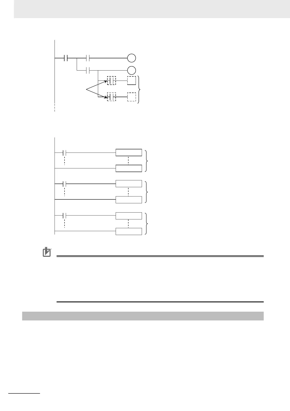
Additional parts
The parts of the ladder
prog
ram that use the data
link area for the relevant
node are processed only
when the corresponding
normal operation flag is ON.
• The following shows an example where data processing is performed only when data links are
operating normally with MC and MCR instructions, or with JMP instructions.
Node B data link
normal operation flag
Node C data link
normal operation flag
Node A data link
normal operation flag
MC
MC
Node A data processing
Node C data processing
Node B data processing
Precautions for Correct Use
Even if an error occurs in communications with a target device, the input data from the target
device will remain stored in words allocated in memory to the local node. T
o prevent malfunc-
tions, write the user program so that no input processing is performed when any of the following
bits of the _EIP_ErrSta (Built-in EtherNet/IP Error) variable is TRUE.
• Major fault: Bit 7
• Partial fault: Bit 6
• Minor fault: Bit 5
7-3-2
Status Flags Related to Tag Data Links
The status of the tag data links is reflected in the following system-defined variables.
7 Tag Data Link Functions
7-84
NJ/NX-series CPU Unit Built-in EtherNet/IP Port User’s Manual (W506)
 Loading...


