3-21
3 Specifications
G5-series AC Servomotors and Servo Drives User’s Manual (with Built-in EtherCAT Communications)
3-1 Servo Drive Specifications
3
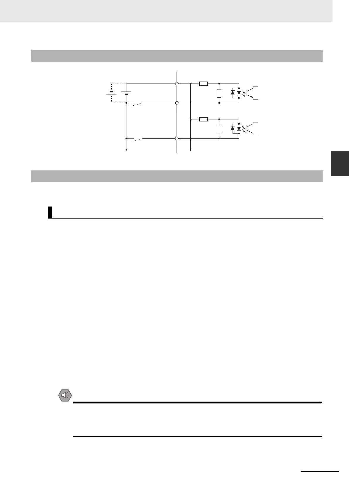
3-1-7 Control Input Circuits
This is the detailed information about the CN1 connector input pins.
Note The functions that are allocated by default are given in brackets.
Refer to 7-1 Sequence I/O Signals on page 7-2 for the allocation procedures.
z Immediate Stop Input (STOP)
• STOP is used when an external sequence such as the host forcibly turns OFF the servo.
• If the Immediate Stop Input (STOP) turns ON during Servomotor rotation, the dynamic brake
makes a deceleration stop. After the motor stops, it remains in servo-free state.
• If the Immediate Stop Input (STOP) turns ON when the motor is energized, an Immediate Stop
Input Error (Error No. 87.0) will occur.
• This input is allocated to the pin 5 with the NC contact in the default setting.
Precautions for Safe Use
Turn ON the Immediate Stop Input (STOP) at the same time as when you turn OFF the main
power. When the main power turns OFF due to an external immediate stop, the motor will
continue to rotate due to residual voltage. This may cause human injury or damage to the
machine and devices.
3-1-7 Control Input Circuits
3-1-8 Control Input Details
General-purpose Inputs (IN1 to IN8)
Pin 5: General-purpose Input 1 (IN1) [Immediate Stop Input (STOP)]
Pin 7: General-purpose Input 2 (IN2) [Forward Drive Prohibition Input (POT)]
Pin 8: General-purpose Input 3 (IN3) [Reverse Drive Prohibition Input (NOT)]
Pin 9: General-purpose Input 4 (IN4) [Origin Proximity Input (DEC)]
Pin 10: General-purpose Input 5 (IN5) [External Latch Input 3 (EXT3)]
Pin 11: General-purpose Input 6 (IN6) [External Latch Input 2 (EXT2)]
Pin 12: General-purpose Input 7 (IN7) [External Latch Input 1 (EXT1)]
Pin 13: General-purpose Input 8 (IN8) [Monitor Input 0 (MON0)]
4.7 kΩ
1.0 kΩ
5
7
IN1
IN2
6+24VIN
To other input circuit
External power supply
12 VDC ± 5% to
24 VDC ± 5%
Power supply capacity
50 mA or more
(per unit)
Signal level
ON level: 10 V or more
OFF level: 3 V or less
To another input circuit GND common
Photocoupler input
4.7 kΩ
1.0 kΩ
Photocoupler input
 Loading...


