4 System Design
4-64
G5-series AC Servomotors and Servo Drives User’s Manual (with Built-in EtherCAT Communications)
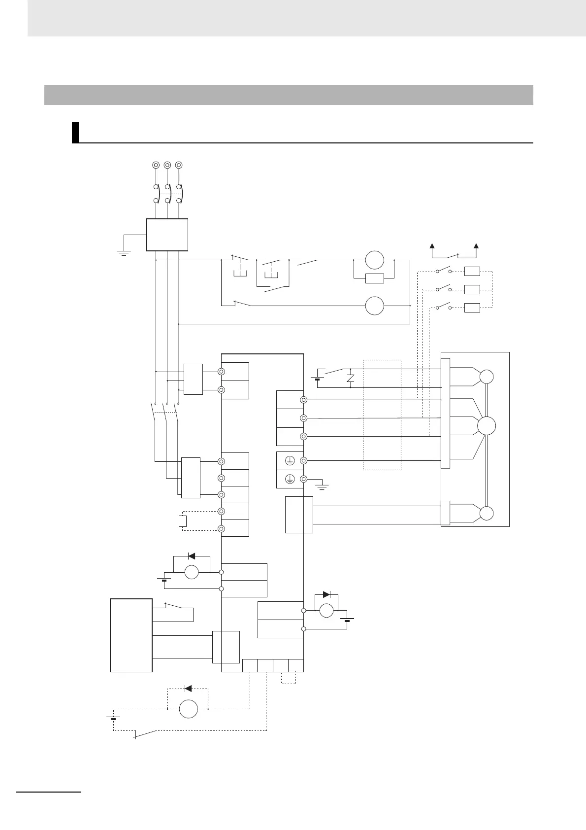
4-5-1 Connection Example for Using DC power Input
R88D-KN75H-ECT (DC power input)
RT
NFB
S
Noise filter
123
456
E
NF
Ground to
100 Ω or less
3-phase 200 to 230 VAC, 50/60 Hz:
PL
Servo error display
L1C
L2C
L1
L2
L3
G5-Series
AC Servo Drive
ALMCOM
/ALM3
4
User-side
control
device
CN1
X
24VDC
24VDC
1
2
BKIR
BKIRCOM
XB
24VDC
Control cables
W
V
U
B
E
M
CN2
Encoder cables
Power cables
24VDC
(*3)
(*2)
CN1
CN1
*1. A recommended product is listed in 4-3, Wiring
Confirming to EMC Directives.
*2. Recommended relay: MY relay by OMRON (24-V)
For example, MY2 relay by OMRON can be used
with all G5-series motors with brakes because its
rated induction load is 2 A (24 VDC).
*3. There is no polarity on the brakes.
*4. When using an externally connected Dynamic
Brake Resistor, remove the short bar from
between DB3 and DB4.
*5. Provide auxiliary contacts to protect the system
with an external sequence so that a Servo ON
state will not occur due to deposition in the
Dynamic Brake Resistor
*6. A Dynamic Brake Resistor of 2 Ω, 180 W is built in.
If the capacity is insufficient, use an external Dynamic
Brake Resistor of 1.2 Ω, 400 W.
Do not use the built-in resistor and an external
resistor at the same time.
*7. Install an external protective device, such as a
temperature fuse. Monitor the temperature of the
external Dynamic Brake Resistor.
*8. Wire the circuit so that the applied voltage between
DB1 and DB2 is 300 VAC/100 VDC or less.
Install a power supply separated from one that
supplies power to CN1.
*9. When using AC power input, include a surge suppressor.
B1
B2
Regeneration
Resistor
TB1
TB1
TB1
X
XB
X
Main circuit contactor(*1)
2MC
1MC
Surge suppressor
(*1)
OFF ON X
1MC
Main circuit
power supply
1MC
AC/
DC
AC/
DC
+
−
+
−
DB1 DB2 DB3 DB4
(*4)
(*8)
(*9)
G5-Series
AC Servo Drive
Ground to
100 Ω or less
(*5) (*6)
(*7)
2MC
 Loading...


