8-3
8 Safety Function
G5-series AC Servomotors and Servo Drives User’s Manual (with Built-in EtherCAT Communications)
8-1 Safe Torque OFF Function
8
8-1-1 I/O Signal Specifications
There are 2 safety input circuits to operate the STO function.
• When safety input 1 or 2 turns OFF, the STO function will start operating within 5 ms of the input, and
the motor output torque will be reduced to 0.
• Connect the equipment so that the safety input circuit is turned OFF to operate the STO function.
• Set the operation when the safety input turns OFF in the Fault reaction option code (605E hex).
Precautions for Correct UsePrecautions for Correct Use
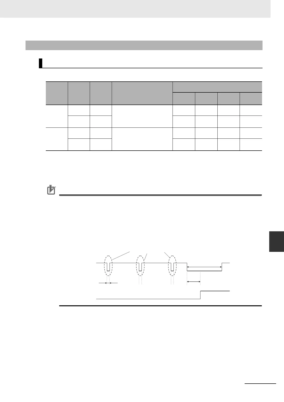
• L pulses for self-diagnosis of safety equipment
When you are connecting a safety device, such as a safety controller or a safety sensor, the
safety output signal of the device may include L pulses for self-diagnosis. To avoid
malfunction due to the L pulses for self-diagnosis, a filter that removes the L pulses is built
into the safety input circuit. If the OFF time of the safety input signal is 1 ms or less, the
safety input circuit does not recognize it as OFF. To make sure that OFF is recognized,
maintain the OFF status of safety input signal for at least 5 ms.
8-1-1 I/O Signal Specifications
Safety Input Signals
Signal
name
Symbol
Pin
number
Description
Control mode
Position
Speed Torque
Fully-
closed
Safety
input 1
SF+ CN8-4 • The upper arm drive signal
of the power transistor
inside the Servo Drive is cut
off.
√√√√
SF− CN8-3 √√√√
Safety
input 2
SF2+ CN8-6 • The lower arm drive signal
of the power transistor
inside the Servo Drive is cut
off.
√√√√
SF2− CN8-5 √√√√
For sel
-diagnosis L pulse
Within 1 ms
Within 5 ms
Normal operation
STO status
Safety input signal
Servo Drive
operation
5 ms or more
 Loading...


