7-35
7 Applied Functions
G5-series AC Servomotors and Servo Drives User’s Manual (with Built-in EtherCAT Communications)
7-9 Gain Switching Function
7
7-9-3 Diagrams of Gain Switching Setting
Switching between Gain 1 (3100 to 3104 hex) and Gain 2 (3105 to 3109 hex) occurs at the following
timing. For the position loop gain, switching occurs based on the setting of 3119 hex.
The details of the gain switching settings vary depending on the control mode used. For the details of
settings available in each mode, refer to Gain Switching Based on the Control Mode on page 7-30.
Instant switching occurs when a gain switching command is issued from the network.
If the absolute value of the command torque exceeds the sum of the Gain Switching Level in Position
Control (3117 hex) plus the Gain Switching Hysteresis in Position Control (3118 hex), the gain switches
to gain 2.
If the absolute value of the command torque exceeds the difference of the Gain Switching Level in
Position Control (3117 hex) minus the Gain Switching Hysteresis in Position Control (3118 hex) for the
time specified in the Gain Switching Delay Time in Position Control (3116 hex), the gain switches back
to gain 1.
7-9-3 Diagrams of Gain Switching Setting
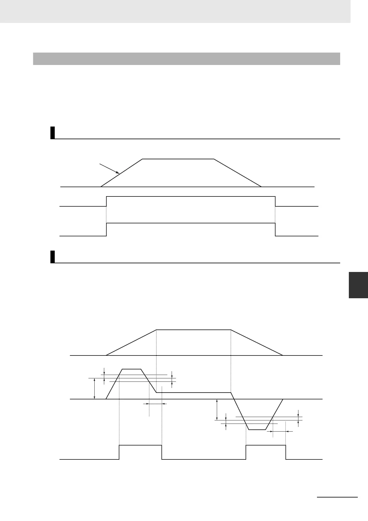
Gain Switching Mode = 2: Gain Switching (GSEL)
Gain Switching Mode = 3: Switching by Command Torque Value
Gain 1
GSEL
Gain 1
Gain 2
Gain switching instruction
Position command
3117 hex
3118 hex
3118 hex
3116 hex
3116 hex
3117 hex
3118 hex
3118 hex
Gain 1
Gain 1
Gain 1
Speed command
Torque
command
Gain 2
Gain 2
 Loading...


