Appendices
A-4
G5-series AC Servomotors and Servo Drives User’s Manual (with Built-in EtherCAT Communications)
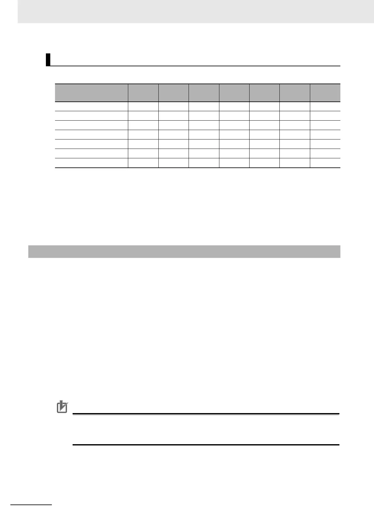
State is indicated by the combination of bits in Statusword (6041 hex), as shown in the following table.
*1 sod = switch on disabled
*2 qs = quick stop
*3 ve = voltage enabled
*4 f = fault
*5 oe = operation enabled
*6 so = switched on
*7 rtso = ready to switch on
G5-series Servo Drives with built-in EtherCAT communications support the following Modes of
operation.
• csp: Cyclic synchronous position mode
• csv: Cyclic synchronous velocity mode
• cst: Cyclic synchronous torque mode
• pp: Profile position mode
• hm: Homing mode
The operation mode is set in Modes of operation (6060 hex). It is also given in Modes of operation
display (6061 hex).
The operation modes supported by the Servo Drive can be checked in Supported drive modes
(6502 hex).
If an unsupported operation mode is specified, a Function Setting Error (Error No. 93.4) will occur.
Precautions for Correct UsePrecautions for Correct Use
• Cyclic synchronous velocity mode, Cyclic synchronous torque mode, and Homing mode are
supported for unit version 2.0 or later.
• Profile position mode (pp) is supported for unit version 2.1 or later.
State Coding
State
Bit 6
sod
*1
Bit 5
qs
*2
Bit 4
ve
*3
Bit 3
f
*4
Bit 2
oe
*5
Bit 1
so
*6
Bit 0
rtso
*7
Not ready to switch on 0 0 × 0000
Switch on disabled 1 1 × 0000
Ready to switch on 0 1 × 0001
Switched on 0 1 × 0011
Operation enabled 0 1 × 0111
Fault reaction active 0 1 × 1111
Fault 0 1 × 1000
A-1-2 Modes of Operation
 Loading...


