4-35
4 System Design
G5-series AC Servomotors and Servo Drives User’s Manual (with Built-in EtherCAT Communications)
4-3 Wiring Conforming to EMC Directives
4
4-3-1 Wiring Method
4-3
Wiring Conforming to EMC Directives
Conformance to the EMC Directives (EN 55011 Class A Group 1 (EMI) and EN 61000-6-2 (EMS)) can
be ensured by wiring under the conditions described in this section.
These conditions are for conformance of G5-series products to the EMC directives. EMC-related
performance of these products, however, may be influenced by the configuration, wiring, and other
conditions of the equipment in which the products are installed. The EMC conformance of the system
as a whole must be confirmed by the customer.
The following are the requirements for EMC Directive conformance.
• The Servo Drive must be installed in a metal case (control panel). (The motor does not, however,
have to be covered with a metal plate.)
• Noise filters and lightening surge absorptive elements (surge absorbers) must be installed on power
supply lines.
• Braided shielded cables must be used for all I/O signal cables and encoder cables. (Use tin-plated,
mild steel wires for the shielding.)
• All cables, I/O wiring, and power lines connected to the Servo Drive must have clamp cores installed.
• The shields of all cables must be directly connected to a ground plate.
*1 Not required for single-phase models with a 100-VAC input.
Note For models with a single-phase power supply input (R88D-KNA5L-ECT/-KN01L-ECT/-KN02L-ECT/-KN04L-
ECT/-KN01H-ECT/-KN02H-ECT/-KN04H-ECT/-KN08H-ECT), the main circuit power supply input terminals
are L1 and L3.
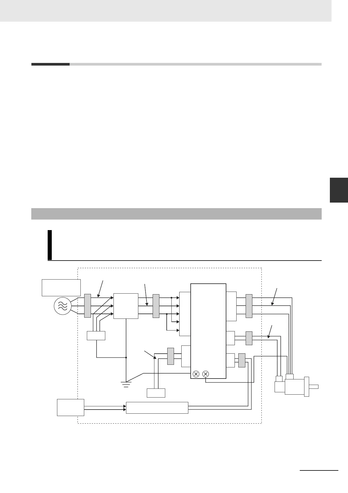
4-3-1 Wiring Method
R88D-KNA5L-ECT/-KN01L-ECT/-KN02L-ECT/-KN04L-ECT/-KN01H-ECT/
-KN02H-ECT/-KN04H-ECT/-KN08H-ECT/-KN10H-ECT/-KN15H-ECT/
-KN20H-ECT/-KN30H-ECT/-KN50H-ECT/-KN75H-ECT/-KN150H-ECT
L1
L2
L3
L1C
L2C
1ø:100VAC
3ø:200VAC
1ø:
100VAC
SG
*1
NF
FC1 FC4
SD
FC3
FC1
CNA
CN1
CNB
CN2
U
V
W
SM
(3)
(4)
(1)
(2)
(6)
(5)
(7)
(8)
FC2
ECAT
IN
FC1
TB
Controller
 Loading...


