R&S OSP Instrument Functions
Operating Manual 1505.3896.12 - 14 86
Up to 3 x SP6T relay, solid state, terminated,
10 GHz
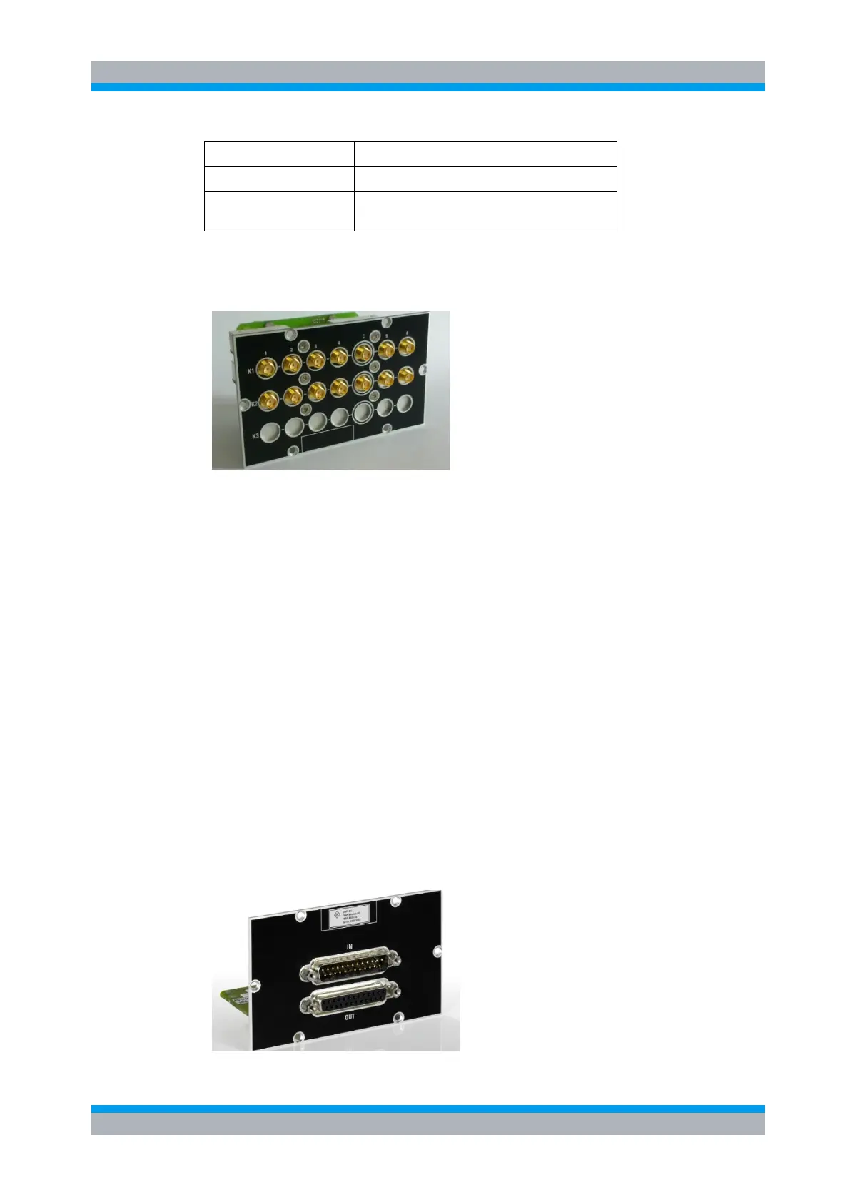
The module R&S OSP-B128 can be configured with up to three SP6T relays. The
relay configuration is with all SMA connectors in-line (flat relay design). See the
following picture.
Figure 5-16: Module R&S OSP-B128
The actual number of SP6T relays fitted in the OSP-B128 can be read from the
module via I2C interface. The R&S OSP automatically recognizes the actual
configuration.
Please note that the relays always must be configured starting from position K1
onwards. In the above picture two relays are fitted; the openings for K3 are covered by
a sheet metal strip.
5.2.3 I/O Module R&S OSP-B103
The module R&S OSP-B103 is a digital I/O module consisting of a 16 bit input and a
16 bit output port.
The input ports are available on the upper D-Sub connector. The input port can be
read at any time. Each input is protected with low-pass and diode against transients.
The output ports are accessible on the lower D-Sub connector. Each output channel is
designed as a FET driver switching to GND when activated. Each output is protected
with diode against transients which may occur when switching inductive loads such as
relay coils.
All output lines can be programmed independently from each other.

 Loading...