R&S OSP Module Interfaces
Operating Manual 1505.3896.12 - 14 210
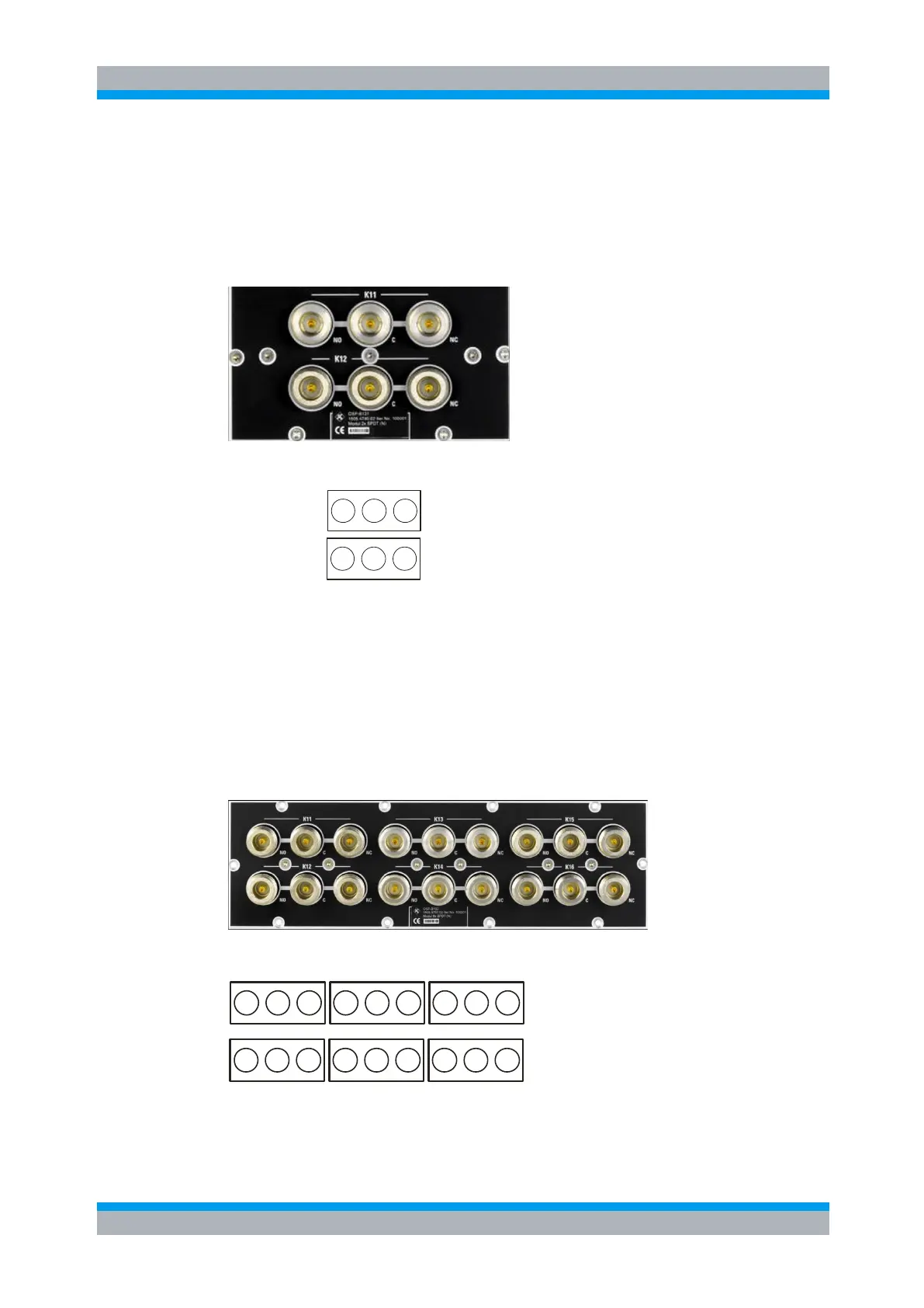
9.2.15 R&S OSP-B131 Interface
The module R&S OSP-B131 contains 2 SPDT relays with N-type female connectors
which are directly accessible at the module’s front panel. There are no additional RF
cables inside the module .
Here is a picture of the R&S OSP-B131:
The following drawing shows the pinout. All RF connectors are N type.
K11
K12
NC
CNO
NC
CNO
K11
K12
NCCNO
NC
CNO
Figure 9-24: Layout RF Connectors of R&S OSP-B131
9.2.16 R&S OSP-B132 Interface
The module R&S OSP-B132 takes two slots in the R&S OSP. It contains 6 SPDT
relays which are directly accessible at the module’s front panel.
All the six relays have N type connectors and are suited for frequencies up to 12 GHz.
There are no additional RF cables inside the module.
Here is a picture of the R&S OSP-B132:
The following drawing shows the pinout.
K12 K14 K16
NC
CNO
NC
CNO
NC
CNO
K11 K13 K15
NC
CNO
NC
CNO
NC
CNO
Figure 9-25 Layout RF Connectors of R&S OSP-B132

 Loading...