Operating Manual 1505.3896.12 - 14 188
2
18
17
+24 V
2-way switch,
1 5/8” EIA
with connector 25
RF connectors,
-pin D-Sub
+24 V
Pos status
15
14
Set A
Set B
2
1
3
4
6
7
8
9
Spinner BN 64 00 75
Electr.
Control
Interlock
Set A
Set B
Set Com
Interlock
Status
22
21
24
25
Carrier Safety Contact
Carrier Safety Contact
GND
RELAY 1 to
RELAY 4
1
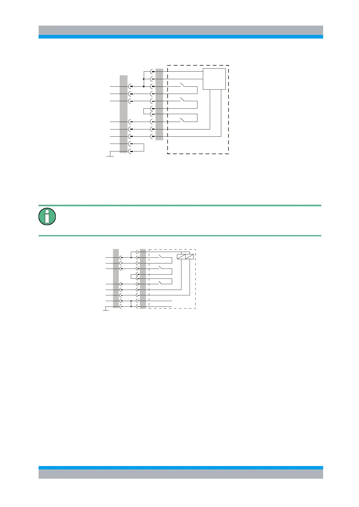
Figure 8-3: Connecting Diagram for BN 64 00 75 to R&S OSP-B104
The connection of the relays of type BN 51 26 70 is done as shown in the block
diagram below.
Please note that in the connecting cable or rather in the corresponding connector the
bridges between pins 8 and 9 on the R&S OSP-B104 side and between pins (1 and
20) and (27 and 29) on the switch side need to be supplied.
20
3
1
+24 V
2-way switch,
with connector
7-16 RF connectors,
37-pin D-Sub
+24 V
Pos status
23
24
22
Set A
GND30
Set B
Set Com
2
1
3
4
6
7
8
9
Spinner BN 51 26 70
Interlock
Set A
Set B
Set Com
Interlock
Status
26
29
27
28
Carrier Safety Contact
Carrier Safety Contact
GND
RELAY 1 to
RELAY 4
Figure 8-4: Connecting Diagram for BN 51 26 70 to R&S OSP-B104
8.5.2 Interlock Monitoring with the R&S OSP-B104
Interlock monitoring with the module R&S OSP-B104 serves two purposes:
● Detect an open interlock circuit and inform the application software
● Relay this information to power amplifiers for deactivating their RF output

 Loading...