Operating Manual 1505.3896.12 - 14 191
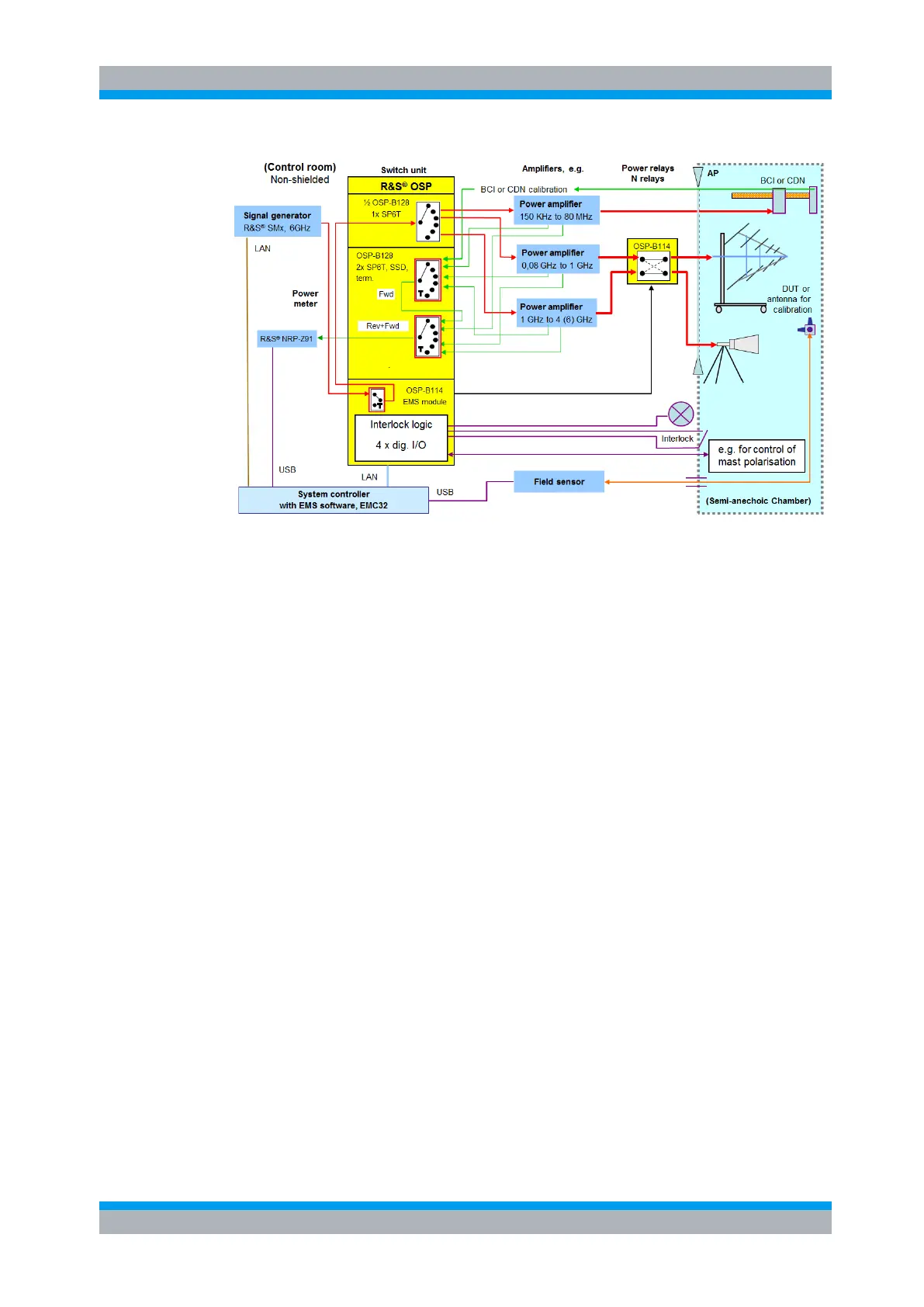
Figure 8-6: Example for an EMS Tests system setup with Module R&S OSP-B114
The above example is setup for Conducted and Radiated Tests with the following
features:
one which can be switched to one of the three power amplifiers
one for Conducted and two for radiated tests
- BCI (Bulk Current Injection) Clamp or CDN (Coupling/
Decoupling Network for Conducted Tests
- two Antennas for Radiated Tests
- can be switched to monitor forward/reverse power of one of the
three amplifiers
- or for calibration
monitor the door contact of the Anechoic Chamber and switch the
power amplifier to Standby with door open.
The Interlock Status can be shown (for example at the Rack front
side)
with suitable pneumatic interface the R&S OSP-B114 output ports
can be used for remote control of antenna polarisation
8.6.1 Switching a Signal Generator via the R&S OSP-B114 module
The module R&S OSP-B114 has one terminated solid state SPDT relay with SMA
connectors. This relay can be looped into the path Signal Generator to Power
Amplifier.

 Loading...