Operating Manual 1505.3896.12 - 14 55
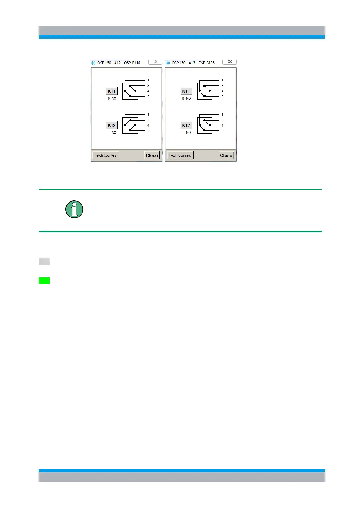
The modules R&S OSP-B116 and OSP-B136 contain two DPDT relays.
Clicking to the symbol of the relay, the position of each relay can be toggled individually.
DPDT switch
When the relay is not activated, terminals 1 - 2 and 3 - 4 are connected. This is the
reset (power on) condition as well. If the relay is activated, the terminal 1 - 3 and 2 - 4
are connected.
The buttons K11 and K12 are not required for manual operation of the switches, but
for defining a path configuration (see chapter 3.4).
Any button K11 and/or K12 in grey color indicates that this relay is not selected. A non
selected relay is not considered when defining a path configuration.
To take over particular relays into the path configuration, the relay buttons must be
selected by clicking on each of the relay buttons required. The selected relay is
displayed with a button in green color. All relays whose relay buttons are selected are
taken over into a path configuration.
Pressing the Shift key while clicking on a relay button will toggle between selecting all
relays of this module and deselecting all of them.
3.3.13 Controlling the R&S OSP-B142
After selection of the R&S OSP-B142 module the following dialog is opened.

 Loading...