Operating Manual 1505.3896.12 - 14 186
3. The path “Path-1” now can be set via the OSP Panel and selecting the utility
>Path >Switch Path … or via remote control (for example with EMC32 software)
by calling the path name Path-1. See chapter 8.1 for details on the EMC32 and
R&S OSP.
8.4.2 Input Ports of R&S OSP-B103
The input ports of the module R&S OSP-B103 are designed for LVC (Low Voltage
CMOS) logic but can be operated with TTL level up to 5 V as well.
Control circuits like the interlock loop as it is used for EMS systems, often make use of
control voltages up to 28 V DC. It is possible to connect the R&S OSP-B103 input to
circuits with up to 28 V when the following points are observed.
The input lines of the R&S OSP-B103 must be connected with a resistor in series if
voltages > 5 V and 28 V DC are applied.
Risk of module damage
The maximum voltage to be directly applied to the module R&S OSP-B103 input lines
is TTL level. For voltages up to 28 V DC, a resistor has to be used in series with a
minimum of 22 kΩ
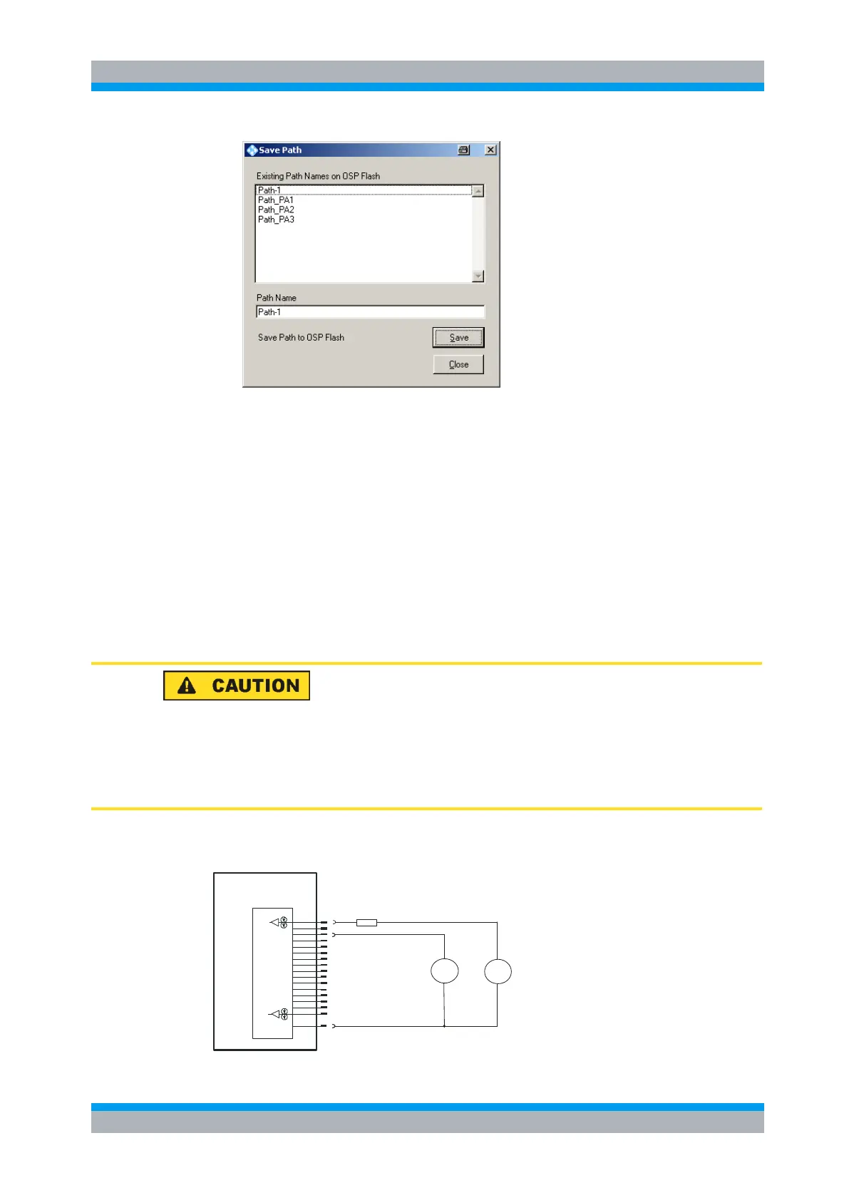
An example for the R&S OSP-B103 input connection with 28 V DC is shown in the
below block diagram.
Module OSP-B103
Input Port
Input connector:
D-SUB male, 25 pin
GND
28V DC
Ch13
Ch15
Ch16
Ch14
Ch6
Ch3
Ch4
Ch5
Ch8
Ch9
Ch10
Ch11
Ch12
Ch1
Ch2
Ch7
3 V DC
max 5 V
Min. 22 Kohm
+
+

 Loading...