R&S OSP Module Interfaces
Operating Manual 1505.3896.12 - 14 207
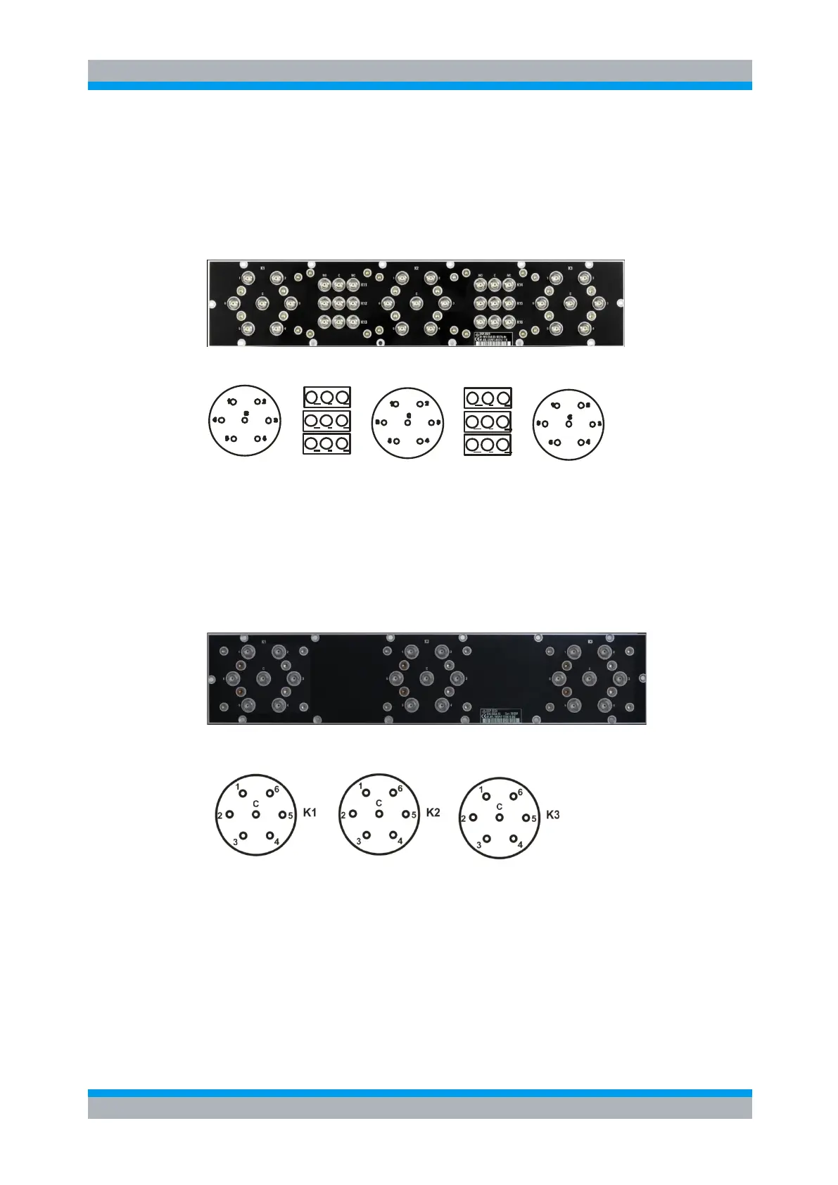
9.2.11 R&S OSP-B125 Interface
The module R&S OSP-B125 takes three slots in the R&S OSP. It contains 6 SPDT
relays and three SP6T relays. All relays are directly accessible at the module’s front
panel. There are no additional RF cables inside the module.
Here is a picture of the R&S OSP-B125:
The following drawing shows the pinout. All RF connectors are SMA female type.
K11
K12
K13
K2
K1
K14
K15
K16
K3
Figure 9-18: Layout RF Connectors of R&S OSP-B125
9.2.12 R&S OSP-B126 Interface
The module R&S OSP-B126 takes three slots in the R&S OSP. It contains three SP6T
relays. All relays are directly accessible at the module’s front panel. There are no
additional RF cables inside the module.
Here is a picture of the R&S OSP-B126:
The following drawing shows the pinout. All RF connectors are SMA female type.
Figure 9-19: Layout RF Connectors of R&S OSP-B126
9.2.13 R&S OSP-B114 Interface
The module R&S OSP-B114 is a single slot module. It houses one DPDT switch with
N-connectors, one SPDT relais with SMA connectors. All relays are directly accessible
at the module’s front panel. There are no additional RF cables inside the module.

 Loading...