R&S OSP Module Interfaces
Operating Manual 1505.3896.12 - 14 211
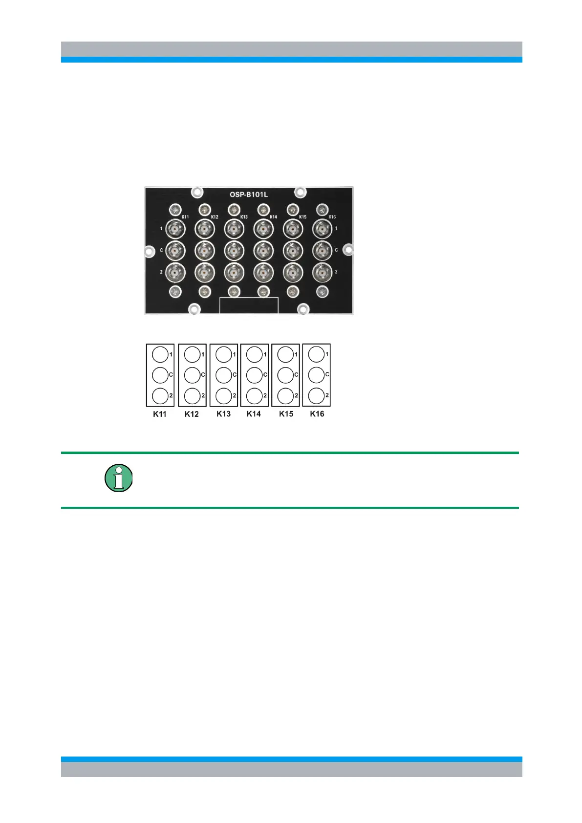
9.2.17 R&S OSP-B101L Interface
The module R&S OSP-B101L is a single slot module. It contains 6 SPDT relays in the
latched version. The relays are directly accessible at the module’s front panel. There
are no additional RF cables inside the module.
Here is a picture of the R&S OSP-B101L:
The following drawing shows the pinout. All RF connectors are SMA female type.
Figure 9-26: Layout RF Connectors of R&S OSP-B101L
SMA Connectors
It is urgently recommended to use an SMA torque wrench (60 Ncm) to screw on and
unscrew the RF connectors from the R&S OSP-B101L module.
In comparison to the module R&S OSP-B101 with monostable relays, the R&S OSP-
B101L relay ports are labelled with 1 and 2, since after power-off, the last relay
condition is maintained. For more information, see chapter 5.2.16.
9.2.18 R&S OSP-B129/-B119 Interface
The module R&S OSP-B129 takes one slot in the R&S OSP. It contains two SPDT
relays and one terminated SP8T relay. The module R&S OSP-B119 houses two SPDT
relays and one non-terminated SP8T relay
All relays are directly accessible at the module’s front panel. There are no additional
RF cables inside the module.
Here is a picture of the R&S OSP-B129:

 Loading...