R&S OSP Instrument Functions
Operating Manual 1505.3896.12 - 14 116
5.3.4 Using the R&S OSP-B101/-B106/-B107/-B111
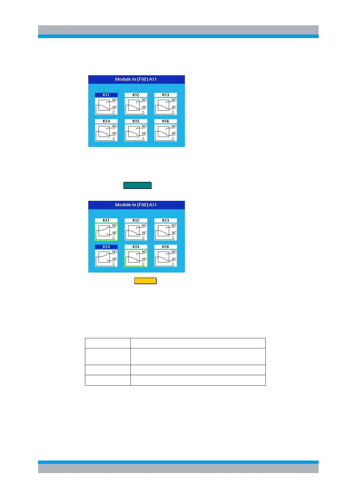
After selection of the R&S OSP-B101 module this dialog is opened.
With the cursor keys one of the six relays can be chosen, indicated by the blue color in
the relay name.
Pressing the FUNCTION key toggles the relay from NC to NO and vice versa. The
display of the switch in the dialog is changed accordingly.
Pressing the key STATUS toggles the selection of the relay.
A selected relay (K11 and K15 in this example) is displayed with a green surrounding.
All selected relays are taken over into a path configuration.
A non selected relay is not considered when defining a path configuration.
The operation as described above applies to further options of the R&S OSP as far as
the option has got a similar relay configuration. It will apply to the following modules:
3 x SPDT relay with N connectors, 12 GHz,
3 x SPDT relays with BNC connectors, 900 MHz / 2 A
6 x SPDT relay, solid state, 6 GHz
Please note that for the module R&S OSP-B106 the relays are numbered from K1 to
K6 but from K11 to K16 for all other modules.

 Loading...