R&S OSP Instrument Functions
Operating Manual 1505.3896.12 - 14 82
Slot A12F Slot A13F
Figure 5-10: R&S OSP150 Version15 Module Slots at front side
Standard Configuration:
The slots in the front side are designated with A12F and A13F. For installation of
modules, the following order is defined as standard:
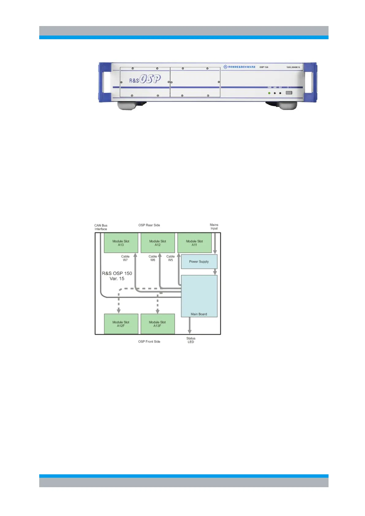
The first module installed from OSP front side always is mounted in slot A13F. From
interface point of view it corresponds to slot A13 (connected via cable W7 – see figure
below).
The second module installed from OSP front side is mounted in slot A12F. From
interface point of view it corresponds to slot A12 (connected via cable W6 – see figure
below).
Figure 5-11: Block Diagram R&S OSP150 Var. 15
Configuration of 2-slot modules:
OSP modules with 2-slot size and requiring two interface cables W6 and W7 (like the
modules OSP-B105/-B115/-B125/-B126) only can be mounted in A12/A13 or
A12F/A13F.
That means with a 2-slot module configured in A12/A13 and one module configured in
the OSP front side, only interface cable W5 (corresponding to A11) is left for A13F).

 Loading...