R&S OSP Instrument Functions
Operating Manual 1505.3896.12 - 14 94
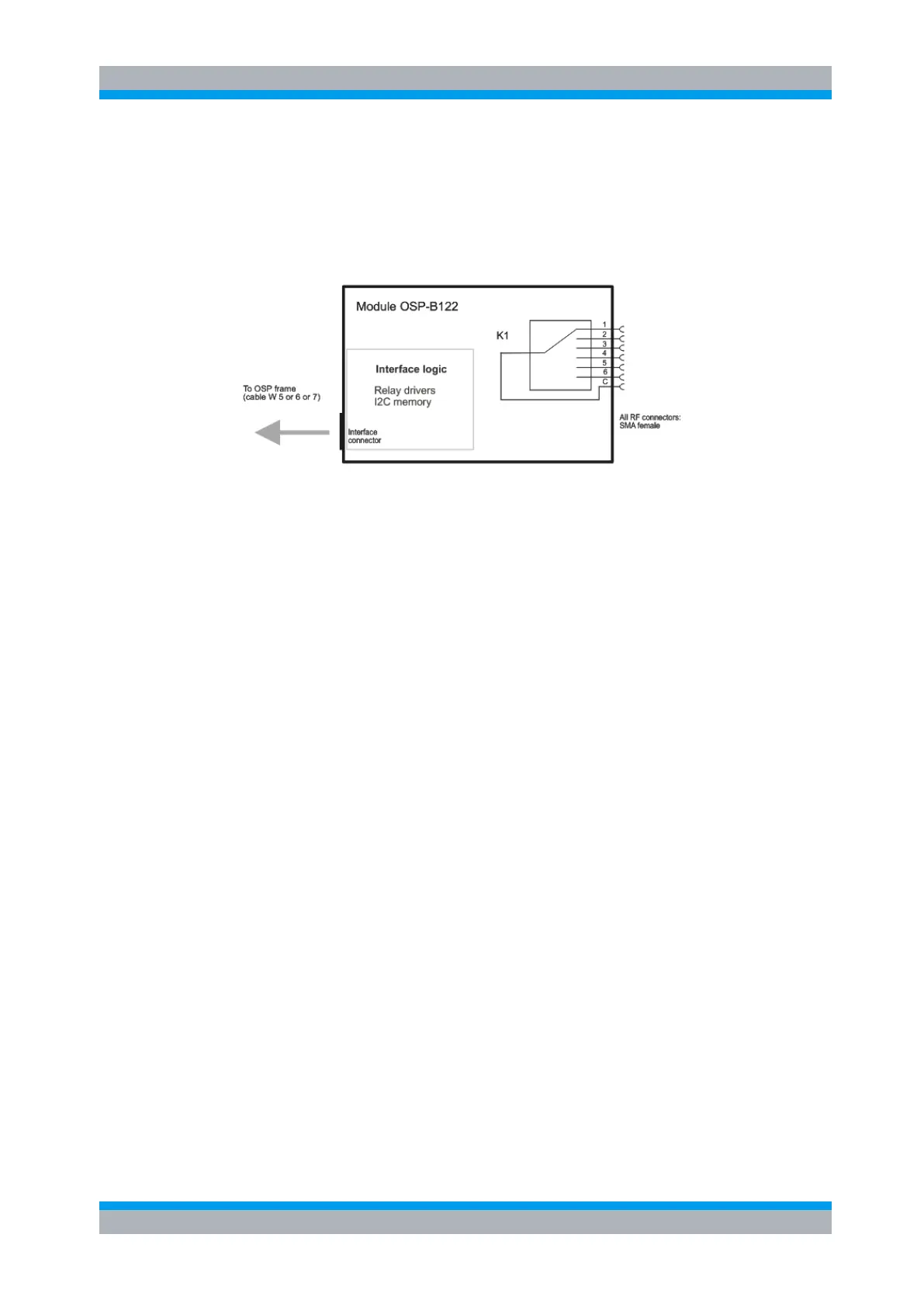
The OSP-B122 module is supplied with power and controlled from the OSP120 via a
single connector on the OSP-B122 printed circuit board. The connection to the
OSP120 is done via a single connection cable.
The OSP-B122 module is equipped with a on board memory to store the necessary
configuration data of the module.
Figure 5-27: Block diagram Module R&S OSP-B122
When the module OSP-B122 is configured within the OSP120, a manual operation of
the module can be performed via the OSP Panel. See chapter 3.3 for details.
For remote control operation see chapters 6 and 7.
Depending on the required switching application, several modules of the OSP-B122
type can be installed in one OSP120.
In the OSP frame a maximum of three modules is possible. If more than three modules
are required, the extension unit OSP150 must be used. For further information on the
extension unit OSP150 see chapter 8.2.
5.2.9 RF Switch Module R&S OSP-B123 and R&S OSP-B124
The module R&S OSP-B123/124 is designed as a universal switching module using
terminated RF relays. The OSP-B123/124 contains the following relay configuration:
6 x SPDT switches (terminated)
3 x SPDT switches (terminated)
1 x SP6T switch (terminated)
2 x SP6T switch (terminated)
The module is designed for independent control of all relay.
The relay is a failsafe type. In case of the SP6T relay, no RF connection is provided
from the terminal C (Common) to one of the six terminals when no voltage is applied
to the relay. To maintain a RF connection between the terminal C (Common) and one
of the six output terminals, a continuous voltage is to be applied to the corresponding
power terminal of the relay.
In case of the SPDT relay, a RF connection is provided from the terminal C (Common)
to the position NC (normally closed) with no voltage applied to the relay. To maintain a
RF connection between the terminal C (Common) and the position NO (normally
open), a continuous voltage is to be applied to the relay.

 Loading...