R&S OSP Instrument Functions
Operating Manual 1505.3896.12 - 14 105
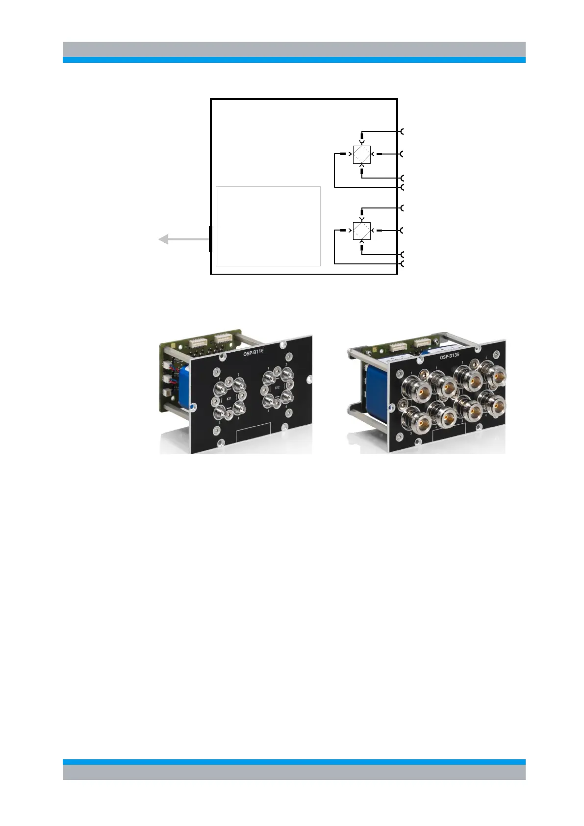
Module OSP-B116
Interface logic
Relay drivers
I2C memory
To OSP frame
(cable W 5 or 6 or 7)
Interface
connector
SMA
DPDT Relays
2
4
3
1
SMA
2
4
3
1
K1
K2
Figure 5-44: Block diagram Module R&S OSP-B116
The module R&S OSP-B136 is equipped with N-connector relays.See following
pictures.
Figure 5-45: Module R&S OSP-B116 and R&S OSP-B136
When the module R&S OSP-B116/-136 is configured within the R&S OSP, a manual
operation of the module can be performed via the OSP Panel. See chapter 3.3.9 for
details.
For remote control operation see chapters 6 and 7.
For details in the application of this module see chapter 8.6.
See chapter 9.2.4 for details on the connector pin assignments.
The R&S OSP-B116/-136 is a one-slot module. Within one OSP base unit up to three
modules of this type can be installed.
5.2.16 RF Switch Module R&S OSP-B101L and R&S OSP-B102L
The modules R&S OSP-B101L and R&S OSP-B102L are designed as a universal RF
switch modules using latched relay types.
The latching relay type will maintain a choosen RF connection wether voltage is
maintained or not after switching is accomplished. The relay switching is done by
applying a voltage pulse to the relay; after that no energy is consumed by this relay
type.

 Loading...