R&S OSP Instrument Functions
Operating Manual 1505.3896.12 - 14 87
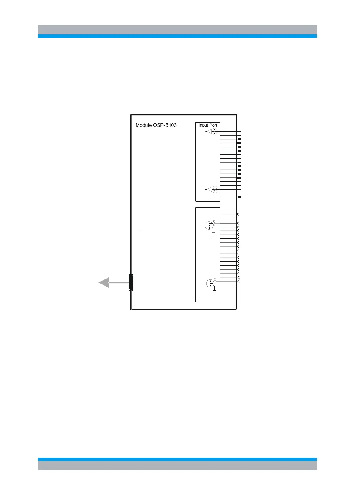
Figure 5-17: Module R&S OSP-B103
The R&S OSP-B103 module is supplied with power and controlled from the R&S OSP
via a single connector on the R&S OSP-B103 printed circuit board. The connection to
the R&S OSP is done via a single connection cable.
The R&S OSP-B103 module is equipped with an on-board memory to store the
necessary configuration data of the module.
Interface logic
Relay drivers
I
2
C memory
Interface
connector
Output Port
Ch6
To OSP frame
(cable W 5 or 6 or 7)
Ch3
Ch4
Ch5
Ch8
Ch13
Ch9
Ch10
Ch11
Ch12
Ch1
Ch2
Ch15
Ch16
Ch7
Ch14
Ch6
Ch3
Ch4
Ch5
Ch8
Ch13
Ch9
Ch10
Ch1
Ch2
Ch15
Ch16
Ch7
Ch14
+28 V
GND
Ch12
Ch11
Figure 5-18: Block Diagram Module R&S OSP-B103
When the module R&S OSP-B103 is configured within the R&S OSP, a manual
operation of the module can be performed via the OSP Panel. See chapter 3.3.9 for
details.
For remote control operation see chapters 6 and 7.
See chapter 9.2.3 for details on the connector pin assignments.
Depending on the required application, several modules of the R&S OSP-B103 type
can be installed in one R&S OSP.
In the R&S OSP frame a maximum of three modules is possible. If more than three
modules are required, the extension unit R&S OSP150 must be used. For further
information on the extension unit R&S OSP150 see chapter 8.2.

 Loading...