R&S OSP Module Interfaces
Operating Manual 1505.3896.12 - 14 203
9.2.5 R&S OSP-B108 Interface
The module R&S OSP-B108 is a single slot module and is designed to switch up to
four DC contacts to one of six positions.
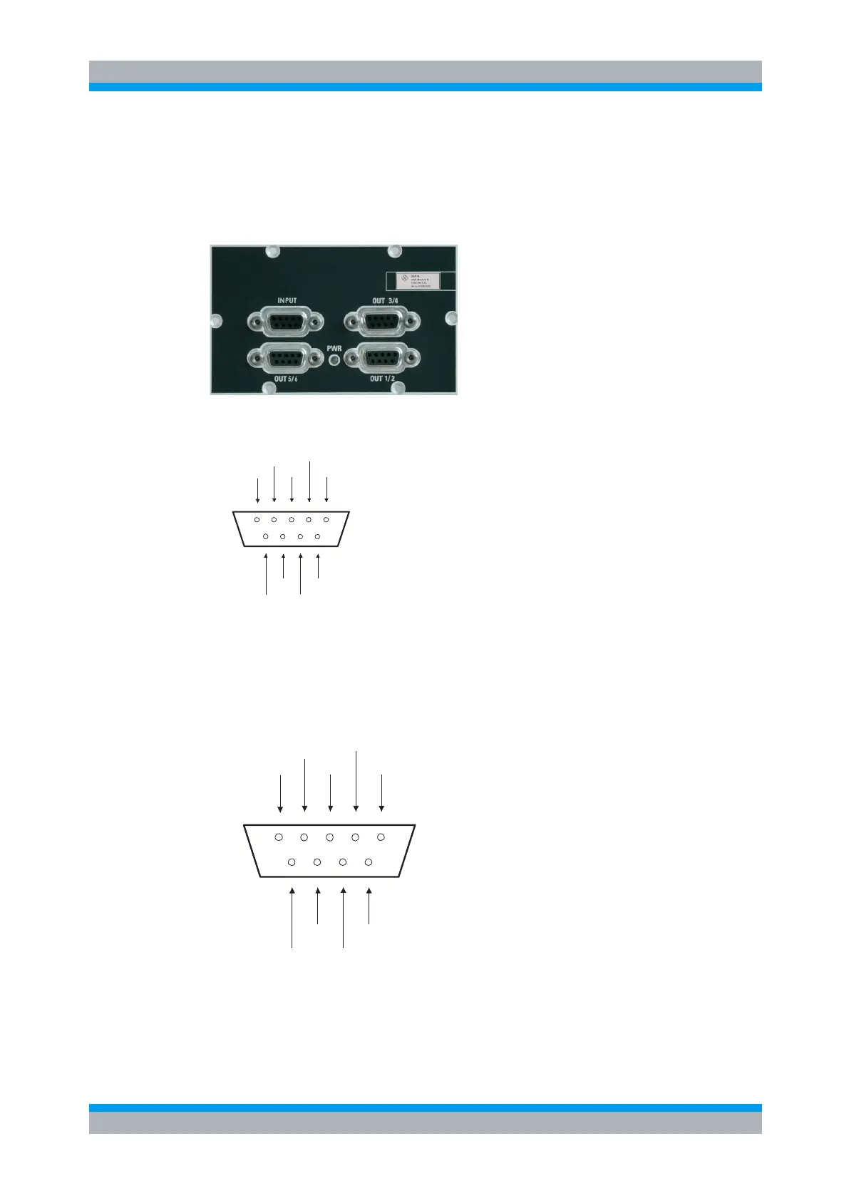
Here is a picture of the R&S OSP-B108:
The connector type INPUT is male, all connector types OUT are D-Sub, 9 pin, female.
The pinout of the INPUT connector is as shown below.
HI_S
LO_F
LO_S
LO_S
GND
LO_F
HI_F
HI_F
HI_S
Figure 9-11: Pin Assignment R&S OSP-B108 INPUT
However the pin names intend functions like HI = positive pole, LO = negative pole, F =
force, S = sense all pins are identical in ability of carrying current.
The pinout of the IN / OUT connector is as shown below. The 1 reflects all odd
numbers of OUT 1,3,5 and the 2 reflects all even numbers of OUT 2,4,6
LO_F1
HI_F2
LO_F2
LO_S2
GND
HI_S2
HI_S1
HI_F1
LO_S1
Figure 9-12: Pin Assignment R&S OSP-B108 Output

 Loading...