R&S OSP Module Interfaces
Operating Manual 1505.3896.12 - 14 204
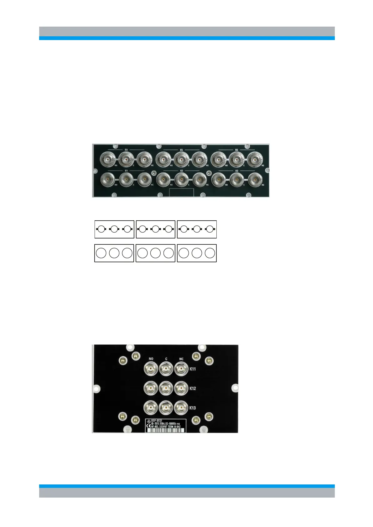
9.2.6 R&S OSP-B106 Interface
The module R&S OSP-B106 takes two slots in the R&S OSP. It contains 6 SPDT
relays which are directly accessible at the module’s front panel.
Three of the relays (K1 to K3) have N type connectors and are suited for frequencies
up to 12 GHz. The other three (K4 to K6) have BNC connectors and may be used up to
900 MHz or for DC currents of up to 2 A. There are no additional RF cables inside the
module.
Here is a picture of the R&S OSP-B106:
The following drawing shows the pinout.
K1 K2 K3
K4 K5 K6
NC
CNO
NC
CNO
NC
CNO
NC
CNO
NC
CNO
NC
CNO
Figure 9-13: Layout RF Connectors of R&S OSP-B106
9.2.7 R&S OSP-B121 Interface
The module R&S OSP-B121 is a single slot module and contains 3 SPDT relays which
are directly accessible at the module’s front panel. There are no additional RF cables
inside the module.
Here is a picture of the R&S OSP-B121:
The following drawing shows the pinout. All RF connectors are SMA female type.

 Loading...