R&S OSP Module Interfaces
Operating Manual 1505.3896.12 - 14 208
The input and output ports are accessible via two connectors type D-Sub, 9 pin. The
female connector type connector is for OUT, the male for IN.
The red LED INTLK shows the status of the interlock loop:
INTTLK LED ON: Interlock loop open
INTLK LED OFF: Interlock loop closed
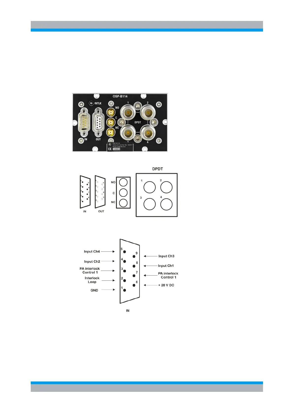
Here is a picture of the R&S OSP-B114:
The following drawing shows the pinout.
Figure 9-20: Layout the Connectors of R&S OSP-B114
Figure 9-21: R&S OSP-B114 Connector IN Pin designation

 Loading...