R&S OSP Instrument Functions
Operating Manual 1505.3896.12 - 14 106
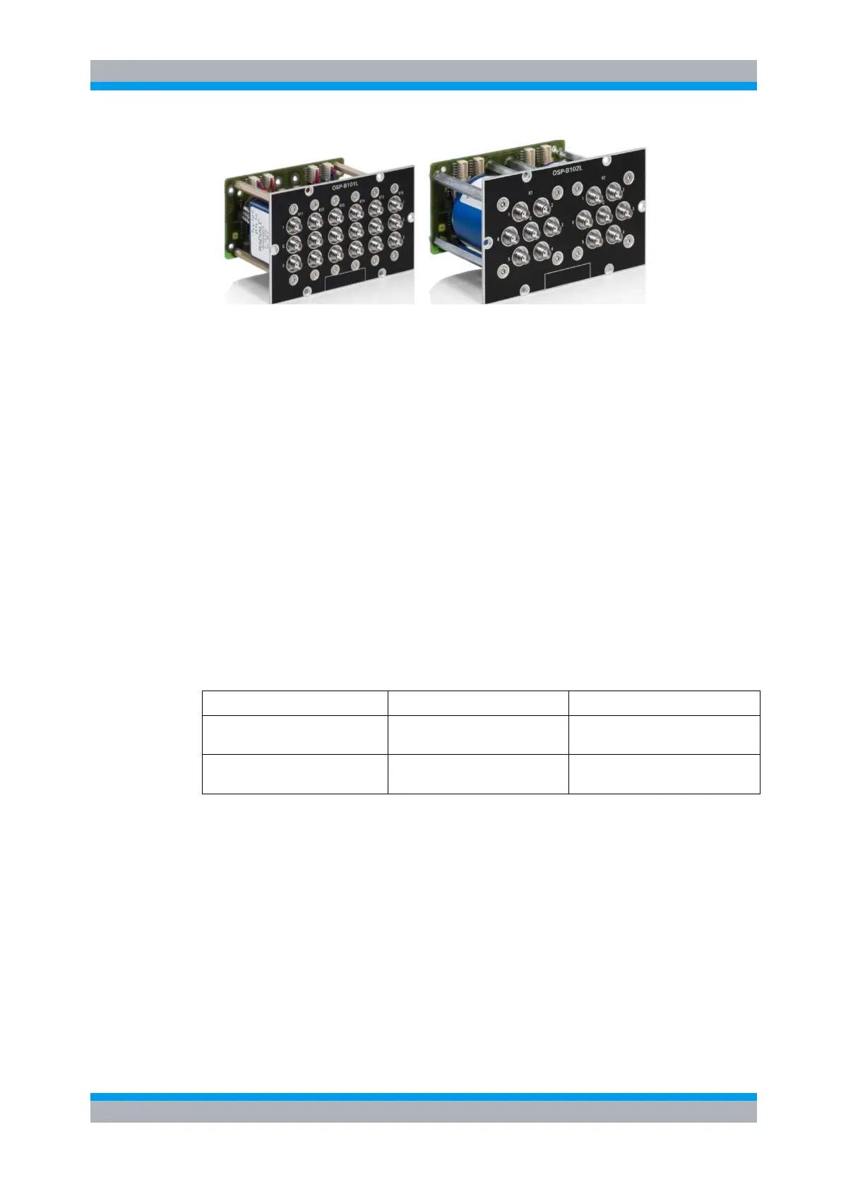
Figure 5-46: Module R&S OSP-B101L and R&S OSP-B102L
The relays are mounted directly in the module front panel. All the RF connectors are
SMA female types. All relays are connected via a short cable to a printed circuit board;
this way the module is of compact size.
Both modules are supplied with power and controlled from the OSP base unit via a
single interface connector on the modules printed circuit board; the connection is just
via a single connection cable.
Both the R&S OSP-B101L and R&S OSP-B102L module is equipped with an on board
memory to store the necessary configuration data of the module.
Port designation:
In comparison to the module R&S OSP-B101 with monostable relays, the R&S OSP-
B101L relays ports are labelled with 1 and 2 since after power off the last relay
condition is maintained..
Latched type relays and Reset Condition:
As already mentioned above, the last relay condition is maintained after power off. The
OPS firmware foresees two possibilities when powering on the R&S OSP. See
following overview:
Reset latched type relays
SPDT relay set to position 2
SP6T relay set to open position
CONFigure:POWerup:RESet ”ON”
Keep latched type relay condition
CONFigure:POWerup:RESet
”OFF”

 Loading...