R&S OSP Module Interfaces
Operating Manual 1505.3896.12 - 14 213
Figure 9-28: Layout RF Connectors of R&S OSP-B142
SMA Connectors
It is urgently recommended to use an SMA torque wrench (60 Ncm) to screw on and
unscrew the RF connectors from the R&S OSP-B142 module.
9.2.20 R&S OSP-PM-I Interface
The module R&S OSP-PM-I takes one slot in the R&S OSP. It allows the integration of
a Power Sensor of the family R&S NRP-Zxx. The Power Sensor is mounted on the
modules base plate and directly connected to the modules N-type feed-through
connector and USB adapter. There are no additional RF cables inside the module.
Here is a picture of the R&S OSP-B129:
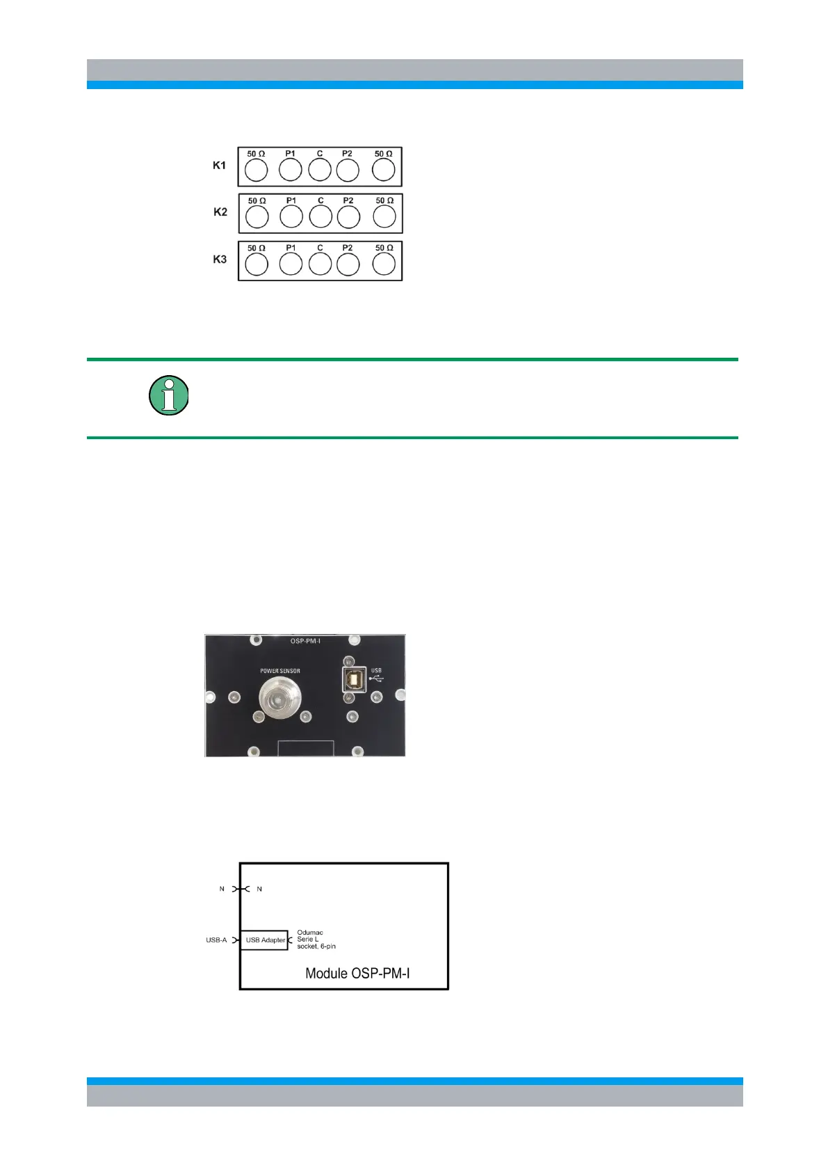
The following drawing shows the connectors available in the module R&S OSP-PM-I.
The RF feed-through connector is N female type. The USB Adapter is specific for R&S
Power Sensors of the family NRP-Zxx. All these Power Sensors are equipped with
Odumac connectors to fit into the USB adapter shown below.
Figure 9-29: Layout Connectors of R&S OSP-PM-I

 Loading...