R&S OSP Preparing for Use
Operating Manual 1505.3896.12 - 14 14
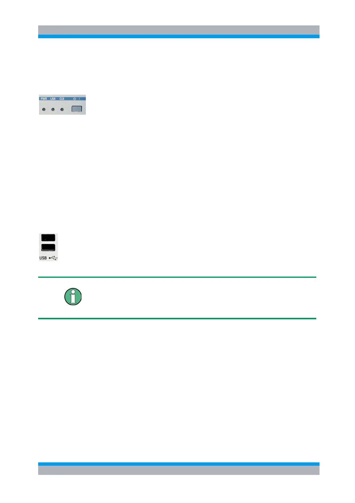
2.1.1 Status LEDs and Standby Key
The status LEDs and the standby toggle switch are located in the bottom right corner
of the front panel. See also chapter 2.5.9.
The status LEDs light to indicate the following instrument states:
PWR: shows standby (yellow LED) and ready state (green LED).
LAN: shows if data are received via LAN network; see Remote Control (chapter 6).
CLK: is flashing if data are transferred via CAN bus.
On an R&S OSP150, the logic is inverted: the CLK indicator goes off shortly during
CAN bus activity.
The STANDBY key serves the following purpose:
Toggle between standby and ready state (indicated by the yellow and green PWR
LED, respectively).
2.1.2 Front Panel Connectors
2.1.2.1 USB Connectors
Single Universal Serial Bus connectors of type A (master USB), used to connect a
keyboard or flash drive. All front panel USB connectors comply with standard USB 2.0;
refer to the "Specifications".
USB Connection
The length of passive connecting USB cables should not exceed 1 m. The maximum
current per USB port is 500 mA. It is recommended to use double-shielded USB
cables.

 Loading...