Interfaces and Connectors
Operating Manual 1505.3896.12 - 14 195
9 Appendix
9.1 Interfaces and Connectors
This chapter provides a detailed description of the rear panel connectors of the
R&S OSP. For a graphical overview of the rear panel refer to chapter 2, Preparing for
Use.
The front panel is also described in that chapter.
9.1.1 Front Panel Connectors
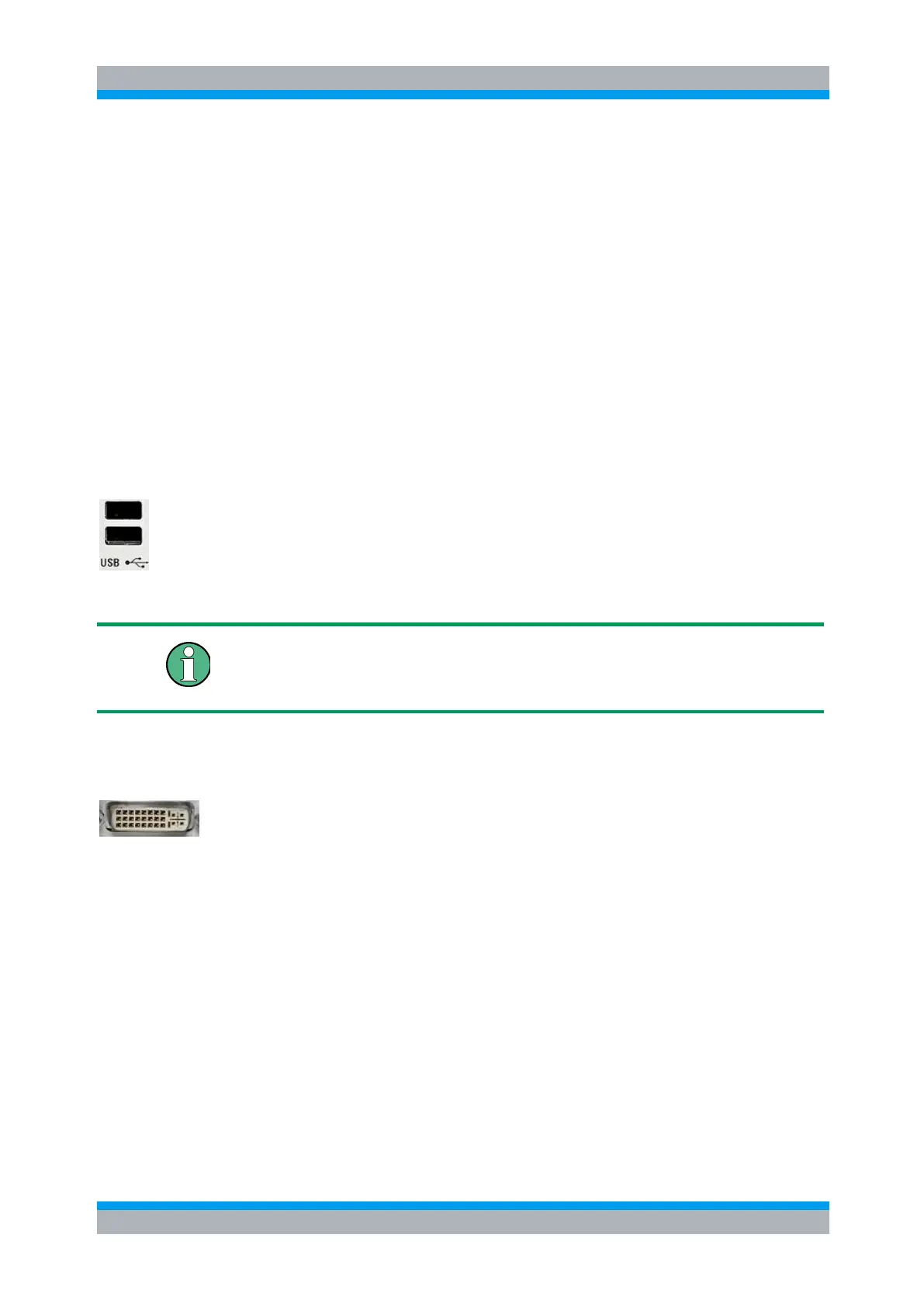
9.1.1.1 USB
Double Universal Serial Bus connectors of type A (master USB), used to connect e.g.
a keyboard or an external storage device (USB flash disk etc.).
The USB connectors comply with standard USB 2.0; refer to the "Specifications".
USB Connection
The length of passive connecting USB cables should not exceed 1 m. The maximum
current per USB port is 500 mA.
9.1.1.2 DVI Interface
Optional DVI-D connector for external monitor connection; see Connecting a Monitor.
This connector is not available on the R&S OSP130 and R&S OSP150.
9.1.2 Rear Panel Connectors
The following chapters describe the interfaces on the rear panel of the R&S OSP (see
also chapter 2.4). The first part deals with the interfaces which are integral part of the
R&S OSP device. The second part describes the interfaces of the modules which can
be configured in the R&S OSP.
9.1.2.1 CAN Bus Connector
The CAN bus connector on rear side of the R&S OSP is used to connect the
R&S OSP120 or R&S OSP130 with the extension unit R&S OSP150.

 Loading...