Operating Manual 1505.3896.12 - 14 56
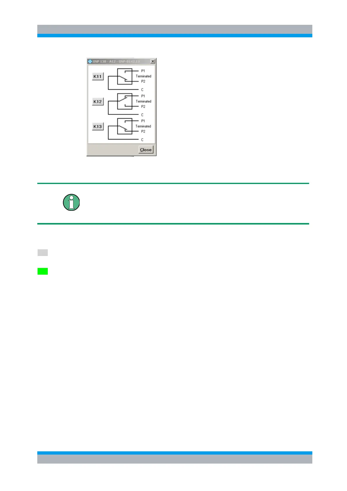
The module R&S OSP-B142 contains a maximum of three SPDT relays.
Clicking to the symbol of the relay, the position of each relay can be toggled individually.
SPDT switch
When the relay is not activated, port C is connected to port P2. This is the reset
(power on) condition as well. When the relay is activated, port C is connected to port
P1.
The buttons K11, K12 and K13 are not required for manual operation of the switches,
but for defining a path configuration (see chapter 3.4).
Any button K11, K12 or K13 in grey color indicates that this relay is not selected. A
non-selected relay is not considered when defining a path configuration.
To take over particular relays into the path configuration, the relay buttons must be
selected by clicking on each of the required relay buttons. The selected relay is
displayed with a button in green color. All relays whose relay buttons are selected are
taken over into a path configuration.
Pressing the Shift key while clicking on a relay button will toggle between selecting all
relays of this module and deselecting all of them.
3.4 Path Configuration
A very comfortable way to define the different switching paths required in a test setup
or in a system is the R&S OSP feature “path configuration”. This utility allows to
combine several relay positions of different R&S OSP modules in one path
information. The path can be named with a suitable name. If path switching is
required, only the path configuration is called by its name and the switching is
performed more or less by a single command.
The advantage to make use of the OSP path configuration utility is:
The switching is called by logical name from the external application (for example
EMC32 software). Using the logical name, the external application does not need to
know the R&S OSP hardware configuration.

 Loading...