R&S OSP Instrument Functions
Operating Manual 1505.3896.12 - 14 84
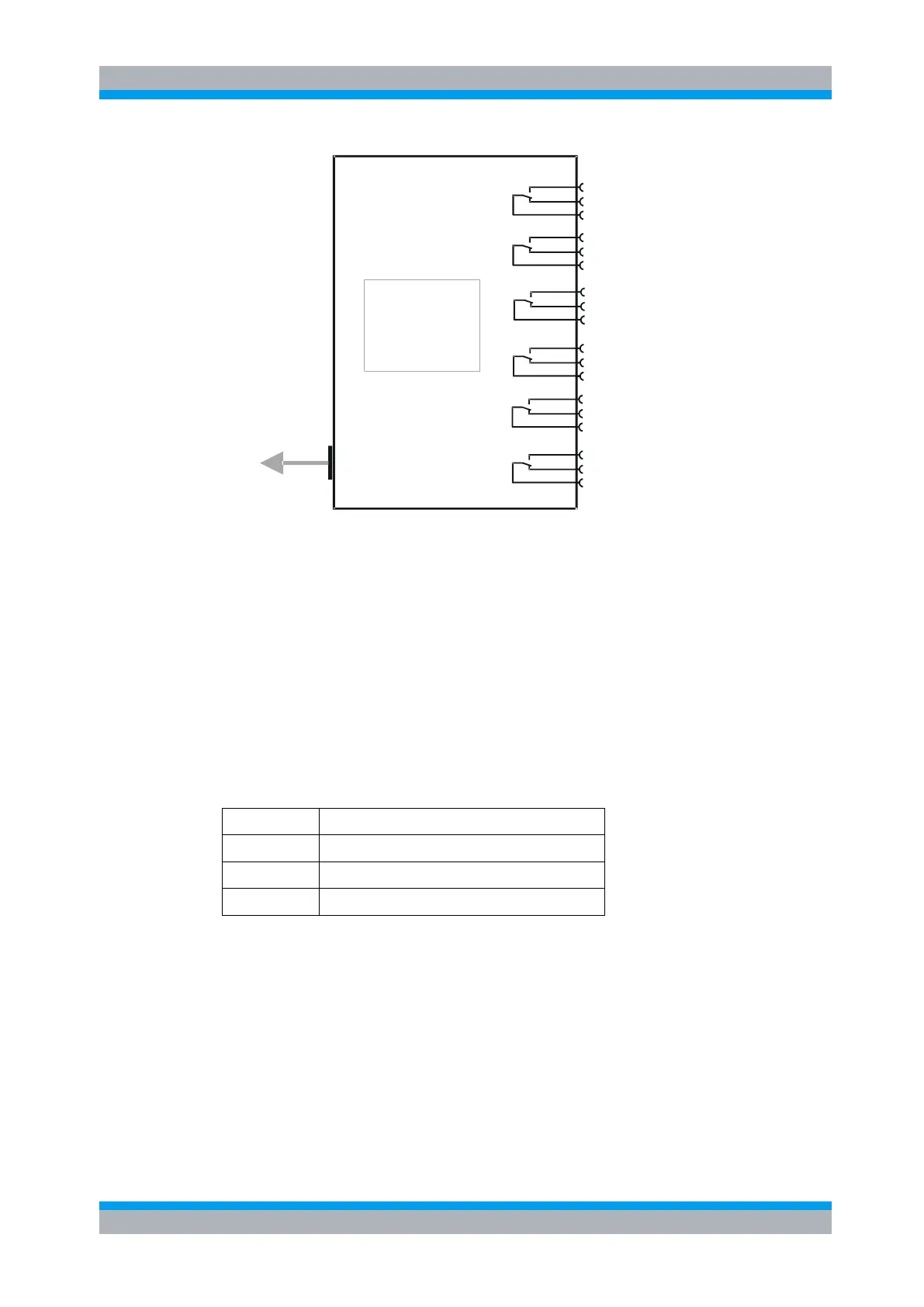
Interface logic
Relay drivers
I
2
C memory
Module OSP-B101
Interface
connector
To OSP frame
(cable W5 or 6 or 7
NO
NC
C
NO
NC
C
NO
NC
C
NO
NC
C
NO
NC
C
NO
NC
C
K11
K12
K13
K14
K15
K16
Figure 5-13: Block Diagram Module R&S OSP-B101
When the module R&S OSP-B101 is configured within the R&S OSP, a manual
operation of the module can be performed via the OSP Panel. See chapter 3.3.6 for
details.
For remote control operation see chapters 6 and 7.
Depending on the required switching application, several modules of the R&S OSP-
B101 type can be installed in one R&S OSP.
In the R&S OSP frame a maximum of three modules is possible. If more than three
modules are required, the extension unit R&S OSP150 must be used. For further
information on the extension unit R&S OSP150 see chapter 8.2.
The description above applies to further options of the R&S OSP as far as the option
has got a similar relay configuration. It will apply to the following modules:
6 x SPDT relay, solid state, 6 GHz
6 x SPDT relay, solid state, terminated, 10 GHz
5.2.2 RF Switch Module R&S OSP-B102/-B112/-B128
The module R&S OSP-B102 and similar as listed above consists of two SP6T
switches. Both switches can be programmed independently from each other.
The relay is a failsafe type; i.e. no RF connection is provided from the terminal C
(Common) to one of the six terminals when no voltage is applied to the relay. To
maintain an RF connection between the terminal C (Common) and one of the six
output terminals, a continuous voltage is to be applied to the corresponding power
terminal of the relay.

 Loading...